


Key Takeaways
- A pneumatic conveying system transports dry bulk solids, powders, granules, and pellets through enclosed pipework on a stream of air or inert gas, removing open handling and airborne dust from the process.
- The two core operating modes are dilute (lean) phase (high velocity, low pressure) and dense phase (low velocity, high pressure). Choosing between them is an engineering decision driven by the material, not by system price.
- Core components: an air mover (blower or compressor), a feeding device (usually a rotary airlock or dome valve), the conveying pipeline, a separator (cyclone or filter receiver), and a discharge point.
- Two numbers govern the whole design: saltation velocity (the speed below which material drops out of suspension) and solids loading ratio (kilograms of material moved per kilogram of air).
- The right system depends on abrasiveness, friability, particle size and moisture, plus conveying distance and required throughput, which is why credible suppliers test the material before quoting.
Walk the floor of an older processing plant, and you can usually tell how the powder gets around: belt conveyors trailing a fine haze of dust, operators scooping material between hoppers, a thin grey film settling on every horizontal surface by the end of a shift. It works, but it spills, it exposes product to contamination, and it puts people right next to the dust.
Pneumatic conveying quietly solved most of that. Instead of physically carrying material on a belt or screw, it uses a moving stream of air inside a sealed pipe to push or pull powders, granules, and pellets from one point to another. No open belts. No spillage trail. No exposed product.
This guide covers what a pneumatic conveying system is, how it works stage by stage, the difference between dilute and dense phase (the single most important design decision you will make), the components involved, and how to specify a system for real industrial conditions.
What Is A Pneumatic Conveying System?
A pneumatic conveying system is a method of moving dry bulk solids through an enclosed pipeline using the force of air or another gas, rather than a mechanical belt, screw or bucket elevator. The material is either fully suspended in the moving airstream or pushed along the pipe in dense slugs, travelling from a source such as a silo, hopper, bulk bag or delivery truck to one or more destinations such as a storage bin, mixer, reactor or packaging line.
The appeal is structural rather than cosmetic. Because the product never leaves the pipe, a pneumatic system reduces contamination, spillage and manual handling in a single stroke. That is why it has become the default across food processing, pharmaceuticals, chemicals, cement, plastics, mining and foundries, where hygiene, safety and product integrity are non-negotiable.
You will also see the same technology sold under different names depending on the application and the region. Pneumatic transporters, material transporters and foundry sand transporters all describe the same underlying principle: enclosed pipe, moving air, controlled transfer.
Why plants are moving away from mechanical conveying
Traditional mechanical conveyors belts, screws, drag chains, bucket elevators have a lot of moving parts in direct contact with the product. More contact surfaces means more wear, more contamination risk, and more manual cleanup.
A pneumatic conveying system is closer to a closed loop: fewer wearing parts touching the product, no open transfer points, and no dust escaping into the plant. That closed-loop character is why food and pharmaceutical auditors tend to favour it, and why it is often the only practical option when a plant needs to route material vertically or around structural obstacles.
How Does A Pneumatic Conveying System Work? (Step By Step)
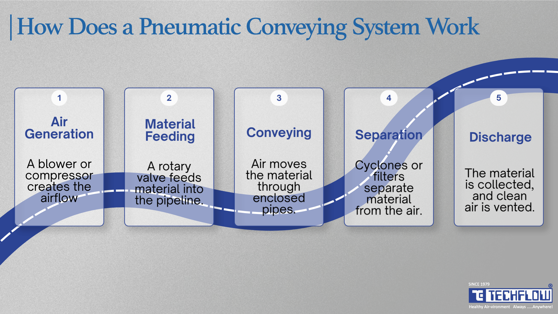
Every pneumatic conveying system runs through five coordinated stages. The sequence below describes a positive-pressure system; in a vacuum system, the material is picked up first, and the air mover sits at the downstream end of the line, but the same five functions are present.
1. Air Generation
A blower or compressor creates the driving force, either positive pressure (pushing air into the line) or negative pressure (drawing air through it). The choice of air mover is one of the most consequential decisions in the whole system, because it sets your available pressure and, with it, your achievable distance and capacity.
2. Material Feeding
The product is metered into the moving air at a feed point, most commonly through a rotary airlock valve or a dome valve, which introduce solids into the pipeline while sealing against pressure loss. In vacuum systems, venturi eductors and flood-feed adapters do similar work.
The feed point is where a surprising number of systems fail in commissioning. Feed too fast, and you choke the line; feed too slow, and you burn energy conveying air. Getting the feeder sized to the air mover, not to the hopper above it, is what keeps a system stable across a shift.
3. Conveying Through The Pipeline
The material travels through the enclosed pipe network either fully suspended in the air (dilute phase) or pushed along as dense plugs separated by air pockets (dense phase). This is where the phase decision changes everything about how the system behaves.
4. Separation
At the destination, the conveyed solids have to be pulled back out of the air. A cyclone separator uses centrifugal force; the air spins rapidly and flings heavier particles against the outer wall, where they drop to the bottom. A filter receiver, typically a pulse-jet bag filter, captures fines on filter media as the air passes through. Many systems run both in series for maximum recovery and to meet emission limits.
5. Discharge
The separated material drops into its final vessel silo, hopper, mixer, or bagging line, usually through another rotary airlock that maintains the pressure boundary, while the now-clean air is vented or filtered.
Those five stages are not interchangeable modules you bolt together from a catalogue. A system tuned for free-flowing plastic pellets looks nothing like one built for abrasive foundry sand or fragile spray-dried food powder. Good design starts with the material and works outward.
Positive Pressure Vs. Negative Pressure (Vacuum) Systems
Beyond the conveying phase, systems are also classified by how the pressure differential is created.
Positive pressure systems push material through the line using air supplied upstream of the feed point. They convey over longer distances and to multiple discharge points at higher capacity, and can blow directly into pressure-tolerant vessels. Positive pressure is consistently reported as the largest technology segment in the market, largely because of its versatility across powders, granules, pellets and fragile substances.
Negative pressure (vacuum) systems draw material through the pipe using a downstream vacuum source, pulling it in from one or more pickup points. Because nothing pressurised can leak out of the line, vacuum systems are often specified purely for cleanliness, particularly when handling hazardous, high-value or dusty materials, or when pulling from several sources into one destination.
Vacuum has a hard ceiling that positive pressure does not: The maximum theoretical differential is one bar (atmospheric pressure), and in practice a positive-displacement vacuum blower gives you around 0.4–0.5 bar of usable differential. That caps both distance and throughput. If a vendor proposes a vacuum system for a long, high-capacity run, ask to see the pressure drop calculation before anything else.
In practice, many plants use a combination: vacuum to gather material from multiple pickup points, then pressure to push it the long haul to storage.
Closed-Loop and Inert Gas Conveying
Where the conveyed material is oxygen-sensitive, explosive, or where solvent vapour must not be released, the conveying gas can be nitrogen rather than air, recirculated in a closed loop. The gas is cooled, filtered and returned to the blower rather than vented. It adds cost and complexity, but for certain pharmaceutical intermediates, fine metal powders and specialist chemicals it is the only compliant option, and it removes the oxygen that a dust explosion needs.
Dilute Phase Vs. Dense Phase Conveying: The Most Important Design Decision
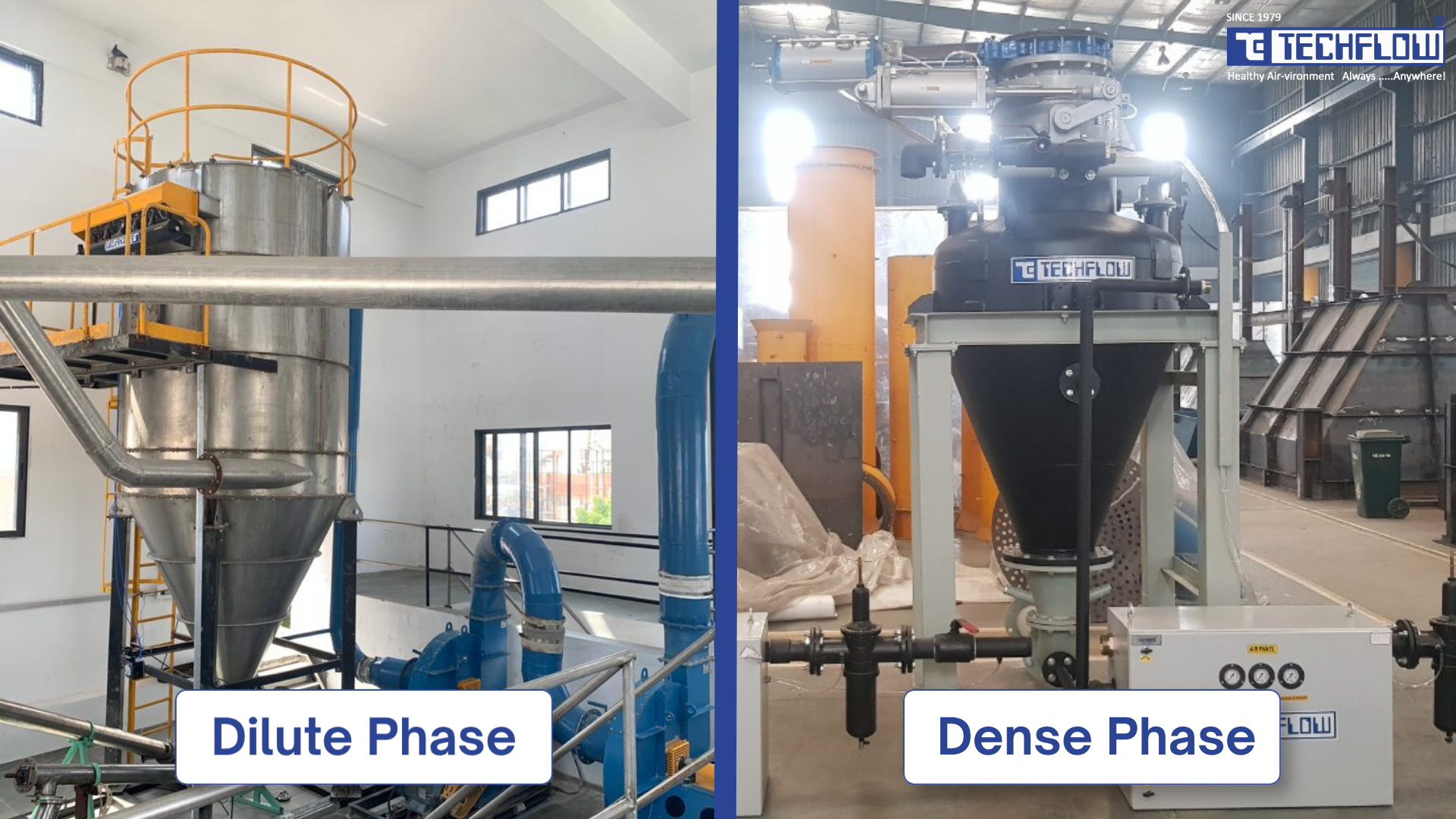
Get the phase wrong and you either shred fragile product and wear out your pipework prematurely, or you over-build and over-pay for a system the material never needed.
Dilute (Lean) phase conveying.
In dilute phase, also called lean phase, the particles are fully suspended in a high-velocity air stream and effectively fly through the pipe.
Working velocities typically fall in the 15–30 m/s range for most powders and granules, rising towards 35–40 m/s for heavy or coarse materials such as mineral grit. Crucially, the floor of that range is not arbitrary: it is set by the saltation velocity of the specific material, the speed below which particles drop out of suspension and settle along the bottom of a horizontal pipe. Design too close to that floor and the line blocks; design far above it, and you pay in wear and energy.
Solids loading is low, typically 2:1 to 10:1, and rarely above 15:1 by mass of solids to air. Operating pressure is modest, usually under 1 barg, which is why a positive-displacement blower is sufficient. Dilute phase is the mode the majority of pneumatic conveyors operate in.
Strengths
- Simpler system architecture and lower upfront equipment cost
- Handles long horizontal and vertical runs and complex routing well
- Excellent for light, free-flowing, non-fragile, non-abrasive materials
- Easy to add multiple discharge points with simple diverter valves
- Continuous conveying rather than batch
Trade-offs
- High velocity means more particle-to-pipe friction, more pipe erosion and more product breakage (attrition), especially at bends
- Higher specific energy cost, because you are moving a lot of air to keep material suspended
- Low solids-to-air loading, so larger pipe and a larger air mover for the same throughput
Dense phase conveying
Dense phase moves material slowly at higher pressure, pushing plugs or slugs of material through the pipe with air pockets between them, rather than suspending individual particles.
Pickup velocities are low, commonly 3–10 m/s, and as low as 1–2 m/s in some plug-flow designs with solids loading of 30:1 to 100:1 or more. Effective dense-phase transport calls for meaningful pressure, typically 3–4 barg (roughly 45–60 psig) for standard duty, and up to 6 barg for long runs or high capacities. This corrects a widespread misconception that a low-pressure blower will do the job; dense phase needs a genuine compressed air supply.
Strengths
- Minimal pipe wear and low product degradation ideal for abrasive and fragile materials
- Prevents segregation of pre-blended mixes, so the recipe arrives as it left
- High achievable capacity and long conveying distances at low velocity
- Very low dust exposure and a small installation footprint
- Far lower air consumption per tonne conveyed
Trade-offs
- Higher capital cost and more complex engineering
- Needs a compressor, not just a blower
- Usually batch rather than continuous, which has to suit the downstream process
- Not every material conveys reliably as a plug; see the Geldart section below
Empty pipe (plug) vs full pipe dense phase
Dense phase is not one thing, and the distinction matters when you are specifying.
Empty pipe (plug flow) systems discharge a batch of material from a pressure vessel as a series of discrete plugs, with air pockets between them, and the line is empty between batches. Plug length is controlled by air injection along the pipeline. This suits materials that naturally form stable plugs, and it is the gentler of the two on the product.
Full pipe (moving bed) systems keep the pipeline continuously charged with material, which moves as a slow, dense, fluidised bed along the bottom of the pipe. Throughput is higher, and the flow is steadier, but the material has to retain air well enough to stay fluidised.
Which one you need is a material property question, not a preference. That is where the Geldart classification comes in.
Geldart classification: why some materials refuse to plug
Geldart's classification groups powders by particle size and density, and it predicts fluidisation behaviour with useful reliability:
| Geldart group | Typical description | Examples | Dense phase behaviour |
|---|---|---|---|
| Group A | Aeratable, ~20–100 µm | FCC catalyst, fine alumina, some flours | Retains air well; excellent full-pipe / moving-bed candidates |
| Group B | Sand-like, ~100–1,000 µm | Foundry sand, silica sand, table salt | Poor air retention; does not naturally form stable plugs; the difficult group |
| Group C | Cohesive, under ~20 µm | Cement, fine fly ash, titanium dioxide | Prone to bridging and channelling; needs careful feeder and aeration design |
| Group D | Spoutable, large or dense | Plastic pellets, grain, coffee beans, gravel | Forms plugs readily; natural plug-flow candidates |
The practical consequence: Group B materials are the ones that catch people out. Foundry sand and silica sand neither retain air like Group A nor form natural plugs like Group D. Conveyed in dense phase without help, they tend to settle and pack until the line blocks. They can be conveyed at low velocity but only with engineered assistance such as pipeline air injection boosters or a bypass line that breaks up over-long plugs before they stall.
This is why "our material is abrasive, so we need dense phase" is only half a specification. The abrasion argues for low velocity; the Geldart group determines whether low velocity is achievable, and what hardware it takes to get there.
This is TECHFLOW's core engineering specialism. Its dense phase pneumatic conveying systems are built specifically for demanding, abrasive duties like foundry sand supplied in both empty pipe (plug) and full pipe configurations, where standard dilute-phase equipment would simply wear out too fast.
Quick comparison table
| Factor | Dilute (lean) phase | Dense phase |
|---|---|---|
| Velocity | High (~15–30 m/s, up to 40 for coarse material) | Low (~3–10 m/s) |
| Pressure | Low (typically under 1 barg) | High (3–4 barg typical, up to 6 barg) |
| Air source | Positive-displacement blower | Compressor |
| Solids loading (SLR) | Low (2:1 to 15:1) | High (30:1 to 100:1+) |
| Material behaviour | Fully suspended in air | Moves as plugs or a moving bed |
| Operation | Usually continuous | Usually batch |
| Best for | Light, non-abrasive, non-fragile | Abrasive, fragile, or pre-blended material |
| Pipe and product wear | Higher | Minimal |
| Air consumed per tonne | High | Low |
| Equipment cost | Lower | Higher |
Specification ranges are indicative and synthesised from standard engineering references (see sources below). Actual design values should always come from material testing.
The Two Numbers That Decide The Design
Strip away the terminology and two figures drive almost every downstream choice.
Saltation velocity is the minimum air velocity at which particles stay suspended in a horizontal pipe. Its vertical equivalent is the choking velocity. Every dilute-phase design is built on a conveying velocity comfortably above saltation for that specific material, typically with a margin of 20% or more, because a line running near saltation is a line that blocks the first time the feed rate wobbles.
Solids loading ratio (SLR), sometimes called the air-to-material ratio, is simply the mass of solids conveyed divided by the mass of air used. It is the cleanest single indicator of which phase you are in: below roughly 15:1 you are in dilute phase, above roughly 30:1 you are in dense phase, and the band between is often called semi-dense or medium phase. Many real installations land in that middle band rather than at either extreme.
If you take away one practical habit from this guide, it is this: ask any prospective supplier for the assumed conveying velocity and SLR before you look at the price. Those two numbers tell you whether the quote is engineered or estimated.
Key Components Of A Pneumatic Conveying System
Whether a system runs dilute or dense, positive or negative pressure, most share the same building blocks.
1. Air mover (blower or compressor): The engine of the system. Positive-displacement (Roots-type) blowers are common for lower-pressure dilute-phase duty, while dense-phase systems typically need compressors capable of sustained higher pressure. TECHFLOW manufactures a full range of centrifugal fans, blowers, and ID/FD fans in-house.
2. Feeding device: Where material enters the air stream. The rotary airlock valve (TECHFLOW's Roto Tuff) is the workhorse; it meters solids from a hopper into the line while sealing against air loss. For higher-pressure and critical-material duty, the dome valve (Dome Tuff) provides a tight, wear-resistant isolation seal where butterfly, ball, or slide-gate valves can't cope.
3. Conveying pipeline: The enclosed pipe network uses mild steel, stainless, or speciality wear-resistant lined pipe for abrasive materials. Long-radius bends are used instead of sharp elbows to cut wear and particle degradation, and on long dilute-phase runs the line diameter is often stepped up in stages to hold velocity steady as the air expands.
4. Separator (cyclone or filter receiver): At the destination, material is separated from the air. A cyclone separator uses centrifugal force to fling particles to the outer wall; a filter receiver (pulse-jet bag filter) traps fines on filter media. Combining both maximises recovery and helps meet emission requirements.
5. Discharge and air lock: The final stage, where separated material drops into its destination vessel again, usually through a rotary airlock that holds the system's pressure boundary.
Because TECHFLOW manufactures each of these components in-house as part of complete, purpose-built systems, the parts are engineered to work together for a specific material rather than assembled from mixed catalogue items that individually look fine but collectively underperform.
What Materials Can Be Conveyed Pneumatically?
Almost any dry, free-flowing or fluidisable bulk solid is a candidate, but the material's behaviour dictates the whole design. Four properties matter most:
- Abrasiveness: Sand, alumina, silica and mineral powders chew through pipe and favour low-velocity dense phase.
- Friability: Crystalline sugars, spray-dried powders, some catalysts and pellets shatter at dilute-phase velocities and need gentler transport.
- Particle size and bulk density: These set pipe sizing, saltation velocity and air mover selection, and they place the material in its Geldart group.
- Moisture and cohesiveness: Wet, sticky or hygroscopic materials bridge in hoppers and block lines. Anything above roughly 2% surface moisture warrants specific testing rather than assumption.
Common real-world duties include cement, fly ash, lime, gypsum, bentonite, clay, alumina, calcium carbonate, soda ash, carbon black, silica, salt, corn starch and food powders, plastic resins, manganese and mineral ores, and foundry sand.
Materials that are wet, sticky, strongly hygroscopic, or very large and heavy are generally unsuited to pneumatic conveying. That is a judgement call worth making before you buy rather than after.
Industries That Rely On Pneumatic Conveying
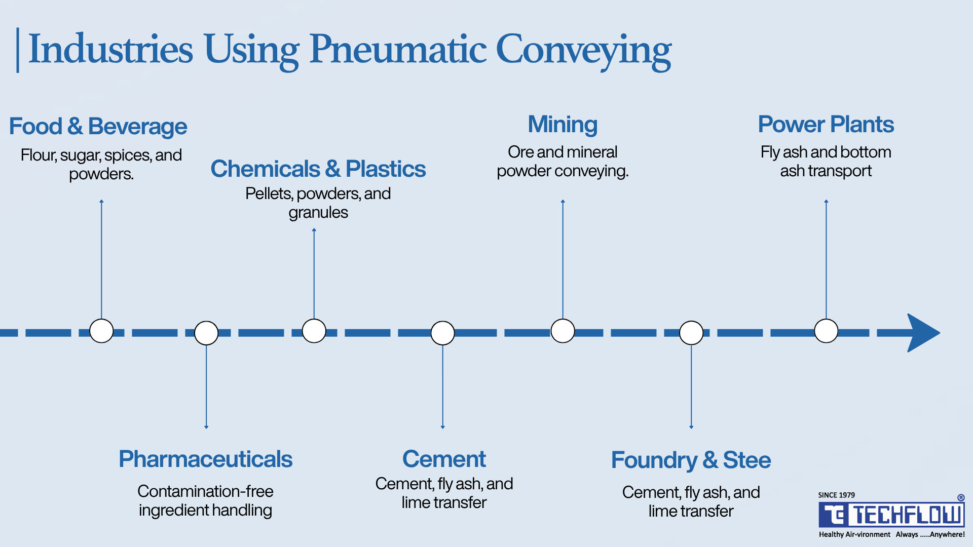
Pneumatic conveying shows up wherever bulk solids need to move cleanly and efficiently:
- Food and beverage: flour, sugar, starch, spices and powdered ingredients, where hygiene and contamination control are non-negotiable.
- Pharmaceuticals: active ingredients and excipients requiring enclosed, contamination-free handling.
- Chemicals and plastics: resin pellets, powders and granules moved from railcars and silos into processing lines.
- Cement and building materials: bulk cement, fly ash and lime from silos to mixing or bagging stations.
- Mining and minerals: ore concentrates and mineral powders across large sites.
- Foundry and steel: sand transport for mould-making and dust handling in integrated steel plants. This is a core TECHFLOW specialism, given how aggressively foundry sand attacks system components.
- Power: fly ash and bottom ash handling in thermal power stations.
Across all of them, TECHFLOW has spent 45+ years engineering enclosed material-handling and air-pollution-control systems for the steel, cement, power, pharmaceutical, food, foundry, and mining sectors.
Pneumatic Conveying Market Size And Growth (2025–2026)
Research firms disagree mainly because they draw the boundary of "the market" differently. Some count only the conveying equipment; others count full engineered systems plus installation and services. That's why you'll see two distinct families of estimates:
- Systems-and-services view: IMARC Group values the global market at USD 34.5 billion in 2025, reaching USD 50.8 billion by 2034 (CAGR 4.27%), with Asia Pacific holding over 30.5% share. Fortune Business Insights puts 2025 at USD 36.89 billion, growing to USD 61.65 billion by 2034 (CAGR 5.87%). The Business Research Company reports USD 34.62 billion in 2025, rising to USD 44.74 billion by 2029 (CAGR 6.6%).
- Equipment-focused view: Global Market Insights estimates USD 8.9 billion in 2025, reaching USD 14.9 billion by 2035 (CAGR 5.3%).
The dollar figures diverge; the direction does not. Every major house agrees the market is expanding at a mid-single-digit CAGR through the mid-2030s, driven by process automation, growth in food and pharma, stricter workplace-safety standards, and Industry 4.0 monitoring. Asia Pacific and North America are the leading regions.
For a plant weighing an upgrade, the practical signal is simple: demand is climbing steadily, and with it, so are equipment lead times from serious manufacturers.
How To Choose The Right Pneumatic Conveying System
This is a multi-variable decision, and it should be made in this order.
1. Material characteristics first, always. Abrasive materials such as foundry sand and minerals push you toward dense phase to protect the pipe. Friable materials push you toward dense phase to protect the product. Particle size, density, moisture, and Geldart group set your velocity, pipe size, and air mover selection. Credible suppliers test the material before quoting anything.
2. Conveying distance and layout. Longer runs with multiple discharge points often favour positive-pressure dilute phase. Shorter, high-capacity, abrasive or fragile duties often favour dense phase. Count the bends as well as the metres each bend adds pressure drop equivalent to several metres of straight pipe.
3. Required throughput, and whether it must be continuous. Dense phase handles higher capacities but usually in batches. If the downstream process needs an uninterrupted feed, that constraint can outweigh everything else.
4. Hygiene and regulatory requirements. Food, pharma, and chemical duty demands fully enclosed, easy-to-clean systems with minimal dead zones, which shapes everything from pipe routing to filter media choice.
5. Energy cost over the system's life. Size the air mover precisely. An oversized blower or compressor wastes energy continuously, not just at start-up, so "just in case" over-specification becomes a permanent tax on the operating budget. Over a ten-year life, energy typically dwarfs the capital difference between two competing quotes.
A Worked Sizing Example
The arithmetic below is illustrative only; it shows the shape of the calculation, not a design. Real numbers come from material testing and a full pressure-drop analysis.
Duty: 10 tonnes per hour of foundry sand, 80 m horizontal, four bends.
Dense phase route
- Assume SLR of 40:1 → air required = 10,000 ÷ 40 = 250 kg/h
- At 3 barg, air density is roughly 4.6 kg/m³ → about 0.013 m³/s actual volumetric flow
- At a 5 m/s conveying velocity → required pipe area ≈ 0.0026 m² → roughly 65–80 mm NB pipe
- Free air delivery required: approximately 3.5 Nm³/min
Dilute phase route, same duty
- Assume SLR of 8:1 → air required = 10,000 ÷ 8 = 1,250 kg/h
- At 0.5 barg, air density is roughly 1.75 kg/m³ → about 0.17 m³/s
- At a 20 m/s conveying velocity → required pipe area ≈ 0.0085 m² → roughly 100 mm NB pipe
- Free air delivery required: approximately 17 Nm³/min
What the comparison shows: the dilute-phase option needs around five times the air volume, a larger pipe and a substantially larger air mover for the same tonnage, and it moves abrasive sand at four times the velocity, against pipe walls and bends. That is the entire case for dense phase on abrasive duty, expressed in numbers rather than adjectives. The counterweight is that the dense-phase system needs a compressor and a pressure vessel, which is where its higher capital cost comes from.
Not sure which phase your material needs?
Send us your material, distance and required tonnes per hour. TECHFLOW's engineering team will run the flow characterisation and come back with a recommended phase, pressure type and component specification. Talk to a TECHFLOW engineer →
Maintenance and Safety Considerations
Pneumatic systems have fewer moving parts than mechanical conveyors, but they are not maintenance-free.
- Filter and bag maintenance: Pulse-jet filters need periodic cleaning and eventual bag replacement to maintain airflow and prevent pressure build-up. Rising differential pressure across the filter is usually the first sign of trouble anywhere in the system.
- Rotary airlock wear: As the primary moving, sealing component, the rotary valve sees the most wear. Rotor tip clearance opens up gradually, air leakage rises, and conveying capacity falls before anything visibly fails, so inspect seal integrity on a schedule rather than on symptoms.
- Pipe and bend wear: In dilute-phase systems handling abrasive material, bends erode fastest. Good designs specify them as replaceable wear-back sections, and good operators track wall thickness rather than waiting for a leak.
- Pressure and flow monitoring: Modern systems increasingly integrate real-time sensors, a trend tied directly to Industry 4.0 adoption and predictive maintenance. A simple trend line of conveying pressure against time will tell you a line is starting to block days before it does.
Combustible Dust: Design It In From Day One
This one deserves its own heading. Many conveyed materials grain, flour, sugar, certain chemical and metal powders form combustible dust, and an enclosed conveying line can become the very confinement that turns a spark into an explosion. The 2008 Imperial Sugar refinery disaster in Georgia began exactly this way: fugitive dust accumulating inside and around conveying equipment.
Internationally, the benchmark is the U.S. National Fire Protection Association framework now consolidated into NFPA 660, which brings the previously separate combustible-dust standards (NFPA 652, 61, 484, 654, 655, 664) under one roof. It centres on a Dust Hazard Analysis (DHA), plus grounding/bonding, explosion venting or suppression, and disciplined housekeeping. In the U.S., these are enforced through OSHA's General Duty Clause and Combustible Dust National Emphasis Program; elsewhere, equivalent local codes apply. The universal rule: combustible-dust protection must be engineered into the system specification at the design stage, never bolted on afterwards. TECHFLOW builds these considerations into applicable system designs from the outset.
Why Work With Techflow
Designing a pneumatic conveying system isn't about picking a blower and running some pipe. It's about understanding material behaviour, plant layout, safety codes, and long-term operating cost together.
TECHFLOW brings 45+ years of engineering experience across Air Pollution Control, Dust Collection, and Pneumatic Conveying, from an 80 sq. m. workshop founded in Ahmedabad in 1979 to a 35,000 sq. m. manufacturing facility serving the steel, cement, power, pharmaceutical, food, foundry, and mining industries in India and worldwide. Its dense-phase pneumatic conveying systems are engineered specifically for demanding, abrasive duties like foundry-sand transport, where standard dilute-phase equipment wears out too quickly.
Whether you need a single-point transfer system or a multi-destination, plant-wide conveying network, TECHFLOW's approach starts with the material itself, testing its flow characteristics before ever specifying pipe diameter, blower size, or separator type.
Moving from mechanical to pneumatic conveying or upgrading an ageing system?
Before you commit to equipment, get the material assessed. TECHFLOW's engineering team designs pneumatic conveying systems around your actual material behaviour, plant layout, and throughput, not a generic template with a particular specialism in dense-phase transport for abrasive and fragile duties like foundry sand.
Talk to TECHFLOW's engineers about your material → Tell us what you're conveying, how far, and how much per hour, and we'll recommend the right phase, pressure type, and component specification.
Frequently Asked Questions (FAQs)
Pneumatic conveying moves material through an enclosed pipeline using air or gas, while mechanical conveying uses belts, screws, or bucket elevators to physically carry material on moving equipment exposed to the environment. Pneumatic systems generally offer better hygiene, lower contamination risk and far more flexible routing. Mechanical systems can be more energy-efficient for very short, straight-line, high-volume transfers.
Neither is universally better; it depends on the material. Dense phase suits abrasive or fragile materials and pre-blended mixes that must not segregate. Dilute phase is usually more cost-effective for lighter, non-abrasive materials over long distances, and it conveys continuously rather than in batches. The deciding inputs are abrasiveness, friability, and the material's Geldart group, which is why material testing beats guesswork.
Dense phase typically requires 3–4 barg (roughly 45–60 psig) for standard duty, rising to around 6 barg for long conveying distances or high capacities. This is well beyond what a positive-displacement blower delivers, so a dense-phase system needs a compressed air supply. A proposal offering dense-phase performance from a low-pressure blower should be questioned.
Positive-pressure dilute-phase systems commonly run several hundred metres, and dense-phase systems can exceed 1,000 m with sufficient pressure and correctly staged pipeline air injection. Vacuum systems are the most limited, typically under 100–150 m, because the usable pressure differential cannot exceed about 0.5 bar. Bends reduce effective distance, so a route with many changes of direction will convey less far than its straight-line length suggests.
Saltation velocity is the minimum air velocity at which particles remain suspended in a horizontal pipe. Below it, material drops out of the airstream, settles along the pipe bottom, and eventually blocks the line. Every dilute-phase design sets its conveying velocity comfortably above the saltation velocity of that specific material, usually with a margin of 20% or more.
Almost any dry, free-flowing bulk solid powders, granules, pellets, flakes and fine particulates including flour, cement, plastic resins, chemical powders, pharmaceutical ingredients, fly ash and foundry sand. Wet, sticky, strongly hygroscopic or very large and heavy materials are generally unsuitable.
Yes, but the phase choice is critical. Abrasive materials should be conveyed in dense phase at low velocity to limit pipe erosion. Foundry sand falls into Geldart Group B, which does not naturally form stable plugs, so a dense-phase system for sand needs engineered assistance such as pipeline air injection boosters or a bypass line, plus wear-resistant or replaceable bends.
Cost varies with distance, capacity, material and phase, so a site-specific quote is the only reliable figure. As a directional guide, a dense-phase system typically carries 1.5 to 2.5 times the capital cost of an equivalent-capacity dilute-phase system, driven mainly by the compressor and pressure vessel. The three variables that move the number most are conveying distance, required tonnes per hour, and whether the material demands wear-resistant pipe and bends. Dense phase often recovers the difference over the system's life through lower energy consumption and far lower wear-part replacement.
They can be, but efficiency depends heavily on correct sizing. Dense phase uses substantially less air per tonne conveyed than dilute phase, though at higher pressure. In either mode, an oversized blower or compressor wastes energy continuously for the life of the plant, which is why a proper engineering assessment matters as much as the technology choice.
Dense phase is used where materials are abrasive (foundry sand, minerals, cement), fragile (crystalline or spray-dried products), or pre-blended and must not segregate. Its low velocity minimises both pipe wear and product breakage while achieving high throughput and low air consumption.
Systems conveying combustible materials, such as flour, sugar, and certain chemical and metal powders, require a Dust Hazard Analysis, proper grounding and bonding, explosion venting or suppression, and disciplined housekeeping. In India this sits under the Factories Act and applicable state rules, with IS/IEC 60079-10-2 governing hazardous area classification; NFPA 660 is the international technical benchmark. All of it must be engineered in at the design stage.
Yes. Closed-loop inert gas conveying, usually with nitrogen, is specified for oxygen-sensitive materials, explosible powders, and processes where solvent vapour must not be released. The gas is filtered, cooled and recirculated rather than vented. It costs more, but it removes the oxygen a dust explosion requires.


