


Key Takeaways
- Centrifugal fans build pressure If air has to fight through ductwork, filters, or a dust collector, you almost certainly need a centrifugal fan. A rough rule of thumb: once total static pressure passes ~500 Pa (2 in. w.g.), start your search with centrifugal designs.
- The impeller decides almost everything. Airfoil and backward-curved wheels win on efficiency in clean air; radial (paddle) wheels win on toughness in dusty, abrasive, or fibrous streams. Matching blade type to your air is the single most important selection call.
- Selection starts with the duty point, not a model number. Required airflow at operating temperature, total system static pressure, and inlet gas temperature come first; everything else follows from those three numbers.
- Fans are constant-volume devices. At a fixed speed, a fan moves the same volume of air, not the same mass. Hot gas is less dense, so sizing at ambient temperature instead of process temperature is a classic, expensive mistake.
- The fan laws make VFDs pay. Power scales with the cube of speed, so trimming a fan to 80% speed cuts power to about half. That's why variable-speed drives beat throttling dampers on energy every time.
- The fan only ever runs where its curve meets your system curve. No calculation moves that point. Confirm it lands in the fan's stable, high-efficiency zone before you buy.
In short: An industrial centrifugal fan moves air by pulling it into the centre of a spinning impeller and flinging it outward, turning the flow 90° and converting that motion into static pressure, the "push" needed to move air through ducts, filters, and dust collectors. Centrifugal fans are selected by duty point (airflow at operating temperature + total static pressure), then by impeller type (airfoil, backwards-curved, forward-curved, or radial), material, and drive. Get the duty point wrong, and even the best fan will underperform.
Here's something most plant managers learn the hard way: a centrifugal fan rarely fails on its own. What fails is the selection. A fan sized for airflow but not pressure. A wheel picked at ambient temperature when the gas runs at 200°C. A high-efficiency airfoil impeller quietly eroding in a dust stream it was never built for. The fan runs; it just runs badly, and the symptoms show up months later as a tripping motor, a whistling scroll, or a baghouse that never quite pulls enough suction.
I've written this guide to help you avoid that. It covers how centrifugal fans actually work, the impeller and construction types that matter in real industrial service, and the part that decides everything: a selection method that starts where good engineers start: with the duty point, not the catalogue.
What Is An Industrial Centrifugal Fan?
An industrial centrifugal fan is a machine that moves air or gas by throwing it outward from a rotating impeller, turning the flow roughly 90° from inlet to outlet and converting rotational energy into static pressure. That pressure-building geometry is the whole point: it's what lets a centrifugal fan push and pull air through resistance long duct runs, filters, dust collectors, scrubbers, and process equipment.
You'll hear the same machine called a centrifugal blower or squirrel-cage fan, and in air-pollution-control work it shows up as an ID (induced draft) fan or FD (forced draft) fan.
In industrial practice, "fan" and "blower" describe the same machine. The name usually follows the job it is doing rather than any difference in design; the same impeller, scroll, and drive can be supplied as a supply-air fan on one line and a dust-collector blower on the next. What actually changes between the two is the duty point: airflow, static pressure, temperature, and the nature of the gas. Those are the numbers worth specifying; the word on the nameplate is just vocabulary.
Centrifugal blowers are built in low, medium, and high pressure classes to match that resistance rather than force a single design to do every job. TECHFLOW's centrifugal blower and fan range is organised around exactly this classification, so a plant can specify the pressure class its ducting actually needs instead of over-sizing the motor to compensate for the wrong fan.
How A Centrifugal Fan Works
The principle is easy to state and surprisingly easy to get wrong in practice. Here's the sequence, start to finish:
- Axial intake: Air enters at the centre (the "eye") of the impeller, moving parallel to the shaft.
- Impeller action: The spinning impeller catches the air between its blades and flings it radially outward. Think of swinging a bucket of water in a circle; the water presses hard against the outer wall and never spills. A centrifugal fan does exactly that, continuously, with air.
- Pressure conversion: The scroll (volute) housing that nautilus-shaped casing collects the fast-moving air and gradually widens toward the outlet. As the passage expands, velocity slows and converts into static pressure. This step is what gives centrifugal fans their pressure advantage over axial designs.
- Radial discharge: The higher-pressure air leaves the outlet at about 90° to the intake, ready to overcome whatever the downstream system throws at it.
That 90° turn inside the scroll isn't a quirk of the design; it's the physical reason a centrifugal fan builds far more pressure than an axial fan of similar size.
Two consequences of this that engineers live by:
- A centrifugal fan is a constant-volume device: At a fixed speed, it moves a relatively constant volume of air, not a constant mass. When gas gets hotter and thinner, the fan still moves the same cubic metres per hour but fewer kilograms, and against different pressure. That's why sizing at the wrong temperature bites so often.
- The fan curve and the system curve rule everything: A fan only ever operates where those two lines cross. No amount of clever arithmetic changes that intersection.
One quirk worth knowing, because it makes underperformance hard to diagnose: if you miswire an axial fan, the impeller spins backwards, and it visibly sucks instead of blows; the error is obvious. Miswire a centrifugal fan, and it still blows air the right way, just weakly. Without an experienced eye, that fault can hide for a long time.
The Fan Laws (Affinity Laws)
If you take one piece of theory away from this guide, make it these three relationships. They describe how a single fan behaves when you change its speed, and they sit behind every VFD decision, sheave change, and troubleshooting call. Per AMCA Publication 201 and the ASHRAE Handbook, for a given fan in a fixed system:
- Airflow ∝ speed: Q₂ = Q₁ × (N₂ / N₁)
- Pressure ∝ speed²: P₂ = P₁ × (N₂ / N₁)²
- Power ∝ speed³: W₂ = W₁ × (N₂ / N₁)³
The cubed law on power is the one that changes how you run a plant. Push a system's volume flow up by 10% and required power climbs by roughly 33%, enough that the motor and supply may need upgrading. Run it the other way and the savings are dramatic: a 20% speed reduction gives about 80% airflow, 64% pressure, and only 51% power; a 50% cut gives 50% flow, 25% pressure, and just 12.5% power. That single relationship is why a variable frequency drive saves so much more than a throttling damper, which chokes the flow while the motor keeps drawing near-full power.
Two cautions that separate real selection from wishful thinking: the fan laws hold only for the same fan in the same system, and only inside its stable operating region. They will not let you compare two different fan models just because both say "centrifugal," and they're dependable only for moderate changes (±20–30%).
Types Of Industrial Centrifugal Fans
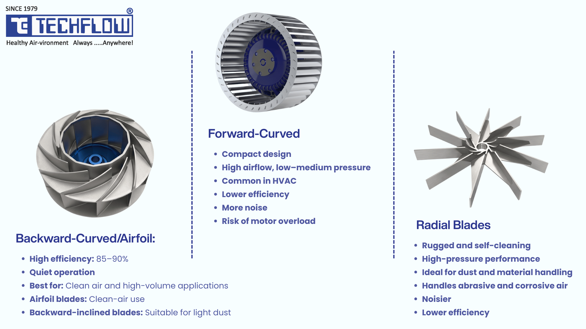
Centrifugal fans get classified in three practical ways: by impeller design, by inlet/width configuration, and by drive arrangement. Each answers a different selection question, and the first one matters most.
By Impeller Design
Blade geometry is the biggest single driver of a fan's pressure, efficiency, noise, and ability to survive dirty air. There are four workhorses.
Backward-curved and airfoil blades curve away from the direction of rotation. Airfoil wheels aerofoil-section blades shaped like an aircraft wing are the efficiency champions, reaching mechanical efficiencies around 85–90%, and they run quietly. They're the right pick for clean-air, high-volume duties: combustion air, HVAC supply, clean process ventilation where energy cost is the priority. Their catch is that those thin aerofoil sections erode and clog in dusty streams. Single-thickness backward-inclined blades give up a little efficiency (~75–80%) for a flat, solid blade that shrugs off light, non-sticking dust. And backward-curved wheels have one genuinely useful trait: a non-overloading power curve: brake power peaks and then falls as flow rises, so the motor is naturally protected from overload.
Forward-curved blades curve toward the direction of rotation, the small, numerous blades of the classic squirrel-cage. They shift large volumes at low-to-medium pressure in a compact housing, which is why they dominate packaged HVAC and air-handling units. The trade-offs: lower efficiency, more noise at pressure, an overloading power curve (power keeps climbing with flow, so the motor can overload if system resistance drops), and zero tolerance for particulate.
Radial (straight / paddle) blades are the rugged specialists. The open, self-cleaning design resists build-up and abrasion and generates the highest static pressure of any centrifugal type. They're the correct, often the only correct, choice for material handling, pneumatic conveying, high-dust-loading exhaust, sawdust and fibre streams, and abrasive or corrosive service. They're loud and less efficient than backward-curved wheels; that's the price of survival in punishing air.
Here's how the four stack up on the attributes that actually decide a selection:
| Impeller type | Pressure | Efficiency | Dust/abrasion tolerance | Power curve | Typical industrial use |
|---|---|---|---|---|---|
| Airfoil | High | Highest (~85–90%) | Poor (clean air only) | Non-overloading | Combustion air, clean HVAC, FD fans on clean gas |
| Backwards-inclined / curved | Med–High | High (~70–80%) | Light dust only | Non-overloading | Clean-to-light-dust process ventilation, ID fans on light loading |
| Forward-curved | Low–Med | Moderate | Poor (clean air only) | Overloading | Packaged AHUs, compact low-pressure supply |
| Radial (paddle) | Highest | Lower | Excellent | Overloading (specify carefully) | Dust collection, pneumatic conveying, fume/flue exhaust, abrasive service |
(Efficiency bands are indicative, general-industry figures always designed to the manufacturer's tested curve for the specific model.)
By Inlet and Width Configuration
- SISW / SWSI (Single Inlet, Single Width): air enters from one side, the standard configuration for most process, ID, and FD duties.
- DIDW / DWDI (Double Inlet, Double Width): air enters both sides of a double-width wheel, delivering roughly twice the flow of a comparable single-inlet wheel at the same diameter, in a compact housing. That's why it's the default inside packaged air-handling units.
By Drive Arrangement
Drive selection is standardised under AMCA Standard 99 / 204 (also recognised as ISO 13349), which defines fan Arrangements 1 through 10.
- Belt-driven fans (Arrangements 1, 3, 9, 10) link motor to fan through sheaves and V-belts. You get speed flexibility: swap a pulley to change fan speed, plus the ability to isolate motor vibration from the ductwork and service the motor without opening the airstream. The cost is a 3–8% transmission loss and ongoing belt tensioning and alignment.
- Direct-driven fans (Arrangements 4, 5, 8) couple the impeller straight to the motor shaft, so the wheel turns at motor speed. Negligible transmission loss, fewer wearing parts, compact footprint, but the speed is fixed unless you add a VFD, and motor vibration transfers more directly into the system.
A field rule that rarely steers you wrong: pick belt drive when you need field-adjustable speed or vibration isolation; pick direct drive when efficiency, compactness, and low maintenance matter most and the duty point is nailed down.
How To Select An Industrial Centrifugal Fan
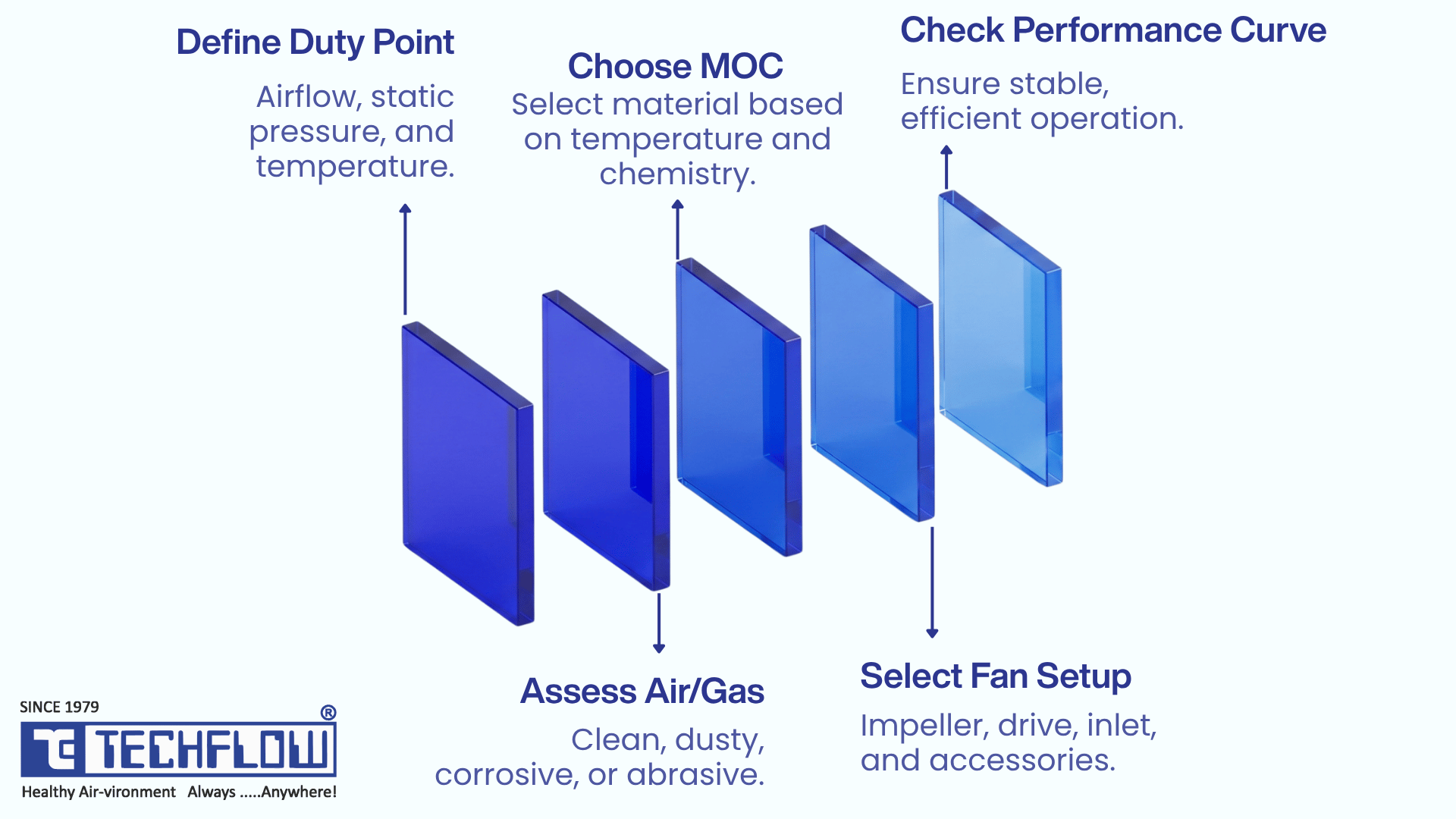
This is where most selections go sideways and where a good one is won. Fan selection doesn't start with a model number. It starts with the duty point. Confirm the parameters below with your process or design team before opening a catalogue or sending an RFQ. Every one of them changes the answer.
Step 1 Define the Duty Point
Required airflow (m³/hr or CFM), at operating temperature, not ambient. Because a centrifugal fan is constant-volume, hot gas takes up more space; a flow figure measured cold will undersize the fan.
Total system static pressure (mmWC or Pa). This is the sum of every resistance the fan has to beat: duct friction, every bend, the pressure drop across filters and the dust collector, hood entry losses, and process equipment. This number, more than any other, tells you whether you even need a centrifugal fan and which impeller. For context, dust-collection systems (bag filters, cyclones) typically need static pressures well above 150–200 mmWC, a range axial fans can't hit reliably. Industrial dust collection commonly runs at 8–18 in. w.g. (roughly 2,000–4,500 Pa).
Operating temperature at the fan inlet. Drives material choice, motor de-rating, and bearing/shaft selection. Standard motors are typically rated for 40°C ambient; hotter airstreams need special motor selection and often shaft cooling.
Step 2 Characterise the Air or Gas
Is the stream clean, dusty, corrosive, vapour-laden, or mixed particulate? If there's dust, quantify the particulate loading (mg/Nm³). This is the fork in the road for impeller choice: clean, high-efficiency duties point to airfoil / backward-curved wheels; dust, fibre, and abrasion point firmly to radial. Running a high-efficiency airfoil wheel in a heavy-dust stream is textbook false economy; the efficiency gain vanishes into erosion, imbalance, and downtime.
Step 3: Select the Material of Construction (MOC)
Corrosiveness and temperature drive the MOC: mild steel for standard duty, stainless steel for corrosive or hygienic service, and special alloys or coatings for aggressive chemistry and high heat. Abrasive streams may call for wear liners or hardened blades.
Step 4 Choose Impeller, Drive, and Configuration
With the duty point and stream defined, the impeller almost picks itself from the comparison table above. Then set the drive arrangement (belt vs direct), the inlet configuration (SISW vs DIDW), and any accessories: inlet dampers or guide vanes, a VFD for variable-flow processes, flexible connectors, anti-vibration mounts.
Step 5: Confirm the Operating Point on the Curve
Last, plot the chosen fan's performance curve against your system curve and confirm the intersection lands in the fan's stable, high-efficiency region, well clear of stall, and not so far out on the curve that power runs away. A fan that hits the airflow number but sits in an unstable part of its curve will be noisy, thirsty, and short-lived.
A Selection Checklist You Can Reuse
Before you send any enquiry to a fan manufacturer, confirm:
- Required airflow at operating temperature
- Total system static pressure (all duct, bends, filters, and equipment)
- Inlet air/gas temperature
- Nature of the gas (clean / dusty / corrosive / vapour-laden)
- Particulate loading, if any
- Required material of construction
- Drive preference (belt or direct) and any VFD requirement
- Noise limits and available installation space
- Inlet and discharge orientation
Where Centrifugal Fans Are Used
Centrifugal fans turn up wherever pressure has to be built against a system, especially across air-pollution-control and process industries:
- Dust collection pulling air through bag filters, cyclones, and cartridge collectors at the high static pressures these systems demand.
- Induced draft (ID) and forced draft (FD) ID fans on the clean or dirty side of baghouses, ESPs, and boilers pull flue gas through to the stack; FD fans push combustion air in. A furnace or induction-furnace pollution-control train typically finishes with a powerful ID fan feeding the duct-and-stack system. This is a deep enough topic that TECHFLOW covers it separately in a dedicated article on PA, SA, FD, and ID fan roles in boiler efficiency; this guide flags the distinction rather than repeating that depth here.
- Fume extraction: welding, laser cutting, soldering, and chemical fume capture, where the fan drives the suction that pulls contaminated air through hoods and filtration.
- Pneumatic conveying: moving light bulk materials (grain, sawdust, plastic pellets) through pipework, usually with rugged radial wheels.
- Process heating, drying, and cooling; HVAC and general building ventilation.
The common thread is resistance. Wherever air has to be pulled or pushed through ducting, hoods, filters, and process equipment, that pressure has to come from somewhere, and that is the job a centrifugal fan is built for.
Centrifugal Vs Axial Fans: Which Does Your System Need?
The deciding factor is resistance, not preference.
- Axial designs move large volumes against very little resistance and hold their efficiency up to roughly 300 Pa. Past that, efficiency falls away, and by around 500 Pa, many are heading toward stall.
- Centrifugal fans take over in that band and above. Wherever air has to travel through ducting, bends, hoods, filters, cyclones, bag houses, scrubbers, or process equipment, static pressure becomes the governing requirement and building static pressure is exactly what the centrifugal geometry does.
So the test is simple: total your system static pressure first. If it clears ~500 Pa (2 in. w.g.), the selection is centrifugal, and the real questions become impeller type, material, and drive. Make that call only after airflow, static pressure, and gas condition are known, never before.
Maintenance And Efficiency Notes
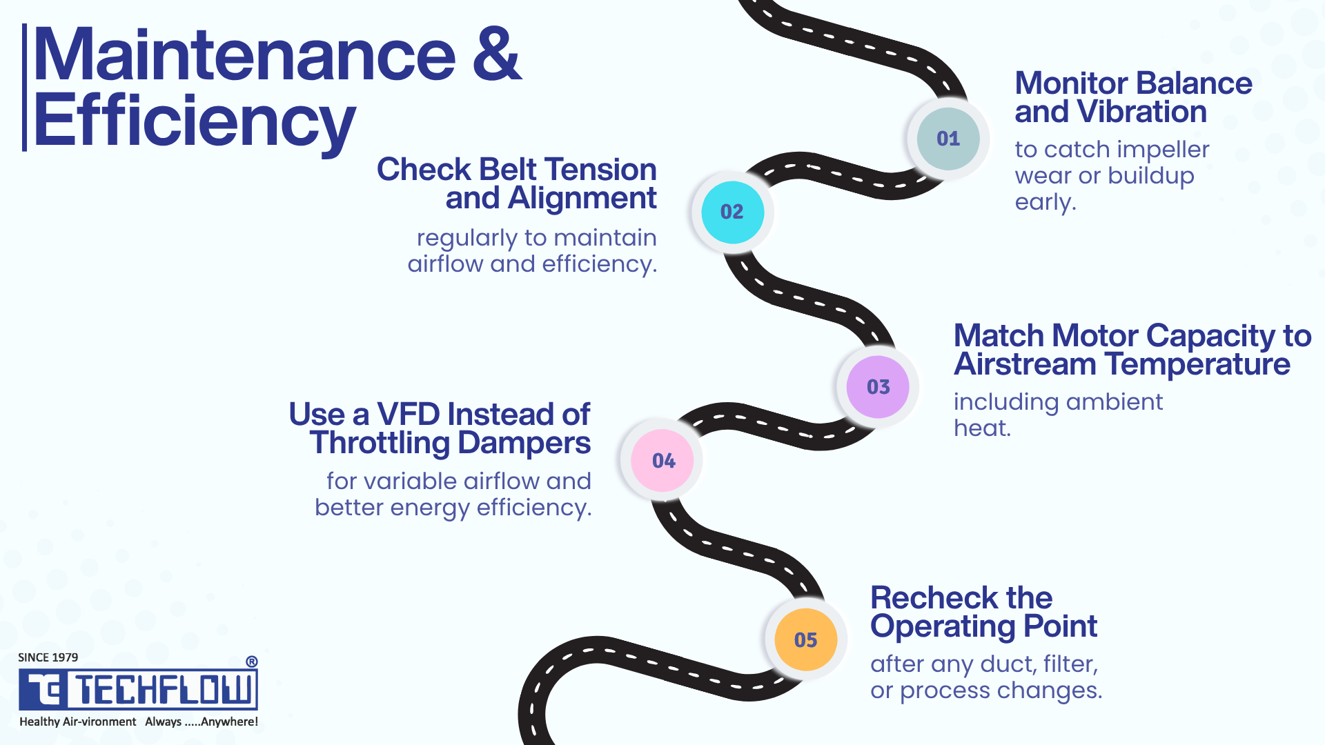
A well-chosen fan still needs care to stay efficient:
- Trend balance and vibration. They're the earliest signs of impeller wear or build-up. Vibration reaching the ductwork often points to a direct-drive arrangement; soften it with flexible connectors and isolation mounts.
- Check belt tension and alignment on schedule. On belt-driven units, these drift over time and quietly erode both efficiency and airflow.
- Match motor thermal capacity to airstream temperature; add the airstream rise to ambient; don't assume a 40°C environment.
- Use a VFD, not a throttling damper, wherever the process needs variable flow. The cubed power law makes speed control far more economical than choking the flow.
- Re-check the operating point after any system change: added ducting, new filters, a different product. The fan follows the system curve; change the system, and you move the point.
Ready To Specify The Right Fan?
Selecting a centrifugal fan is an engineering decision, not a catalogue pick. Share your duty point airflow at operating temperature, total static pressure, gas characteristics, and temperature, and our application engineers will recommend the correct impeller, material, and drive for your process. Talk to TECHFLOW for a fan selection built around your air-pollution-control or process application.
Frequently Asked Questions (FAQs)
It draws air in axially at the centre of a spinning impeller, uses centrifugal force to fling that air outward and speed it up, then converts the speed into static pressure inside a scroll-shaped housing before discharging it at about 90° to the intake. That pressure conversion is exactly why centrifugal fans are so good at moving air through ducts, filters, and resistance.
An axial fan moves air parallel to its shaft and delivers high volume at low pressure, which only works where system resistance is very low. A centrifugal fan turns the air 90° and builds high static pressure, best for pushing air through ductwork, filters, and dust collectors. A quick test: if total static pressure is above ~500 Pa (2 in. w.g.), start with a centrifugal fan.
By impeller design, there are four: airfoil, backward-inclined/curved, forward-curved, and radial (straight/paddle). Airfoil and backward-curved wheels are the most efficient and suit clean, high-volume air; forward-curved wheels are compact and common in packaged HVAC; radial wheels build the highest pressure and handle dust, abrasion, and material handling.
They are the same machine built for different amounts of system resistance. Low-pressure units suit short, open duct runs and general ventilation. Medium-pressure units cover typical ducted process ventilation and lighter filtration. High-pressure units are built for long duct runs, heavy filtration, cyclones and bag houses, and pneumatic conveying where static pressure, not airflow, is the limiting number. Specifying by pressure class is what stops a plant from over-sizing a motor to compensate for a fan that was never built for the resistance in front of it.
Dust collection needs high static pressure, usually well above 150–200 mmWC, and an impeller that resists build-up and abrasion. A radial wheel (or, for lighter loading, backward-inclined) is the right choice. Forward-curved and airfoil wheels are clean-air designs and shouldn't be used in dusty streams.
Start with the duty point: required airflow at operating temperature, total system static pressure (summed across all ducting, bends, filters, and equipment), and inlet gas temperature. Then characterise the gas and particulate loading, choose the material of construction, select impeller and drive, and confirm the operating point sits in the fan's stable, high-efficiency region on its performance curve.
The fan (affinity) laws describe how one fan behaves as its speed changes: airflow varies directly with speed, pressure with speed squared, and power with speed cubed. They're essential for sizing VFDs and predicting performance without re-testing, but they apply only to the same fan in the same system, and only across moderate speed changes.
Choose belt drive when you need field-adjustable speed or want to isolate motor vibration from the ductwork. Choose direct drive for higher efficiency, a compact footprint, and lower maintenance when the duty point is well defined. Direct drive avoids the ~3–8% belt transmission loss but fixes fan speed unless you fit a VFD.
Common culprits are an underestimated system static pressure (the real resistance is higher than the fan was sized for), the wrong impeller for the duty, a reversed-rotation wiring error (a centrifugal fan still blows the right way when miswired, just weakly), slipping or worn belts, or a clogged/eroded impeller. Because the fan only runs where its curve meets the system curve, an unexpected shortfall usually means the actual system curve differs from the design assumption.


