


Key Takeaways
- An industrial dust collector retrofit upgrades selected parts, such as media, cleaning, fan, or controls, while the existing collector body stays in service.
- Evaluate a retrofit first when the casing, tubesheet, hopper, and supports are in good condition and the shortfall traces to specific components, not the collector's size.
- Consider replacement when required airflow exceeds what the casing can filter at a workable air-to-cloth ratio, or the structure is badly corroded.
- Faults that return after a correct repair point to a design mismatch; one-off faults that clear after repair are maintenance, not retrofit cases.
- Base every retrofit on measured airflow, pressure profile, gas temperature, moisture, and dust data, and verify the same values after commissioning.
- Fix airflow and distribution first, then media and cleaning, then controls; new media on a system with the wrong airflow simply moves the problem.
- If the dust is combustible, review the dust hazard analysis under NFPA 660 before changing airflow, filters, ducting, or hoppers.
Retrofit Or Replace? The Short Answer
Over a collector’s life, production goes up, a new furnace or mill is tied into the same duct, the fuel changes, and emission limits tighten. In India, for example, the Environment (Protection) Amendment Rules, 2015, notified on 7 December 2015, set tiered particulate limits for thermal power plants, down to 30 mg/Nm³ for units installed from 2017. A collector that met its original duty can fall short of the emission standards required today.
Plant teams then have to decide whether the existing system needs complete replacement or whether a retrofit can restore performance and meet current requirements.
Evaluate a retrofit first when the collector's housing, structure, and hopper are sound, and the shortfall can be traced to specific components, such as filter media, the cleaning system, the fan, ductwork, dust discharge, or controls. Evaluate complete replacement seriously when the required airflow or emission limit exceeds what the existing casing can deliver at a workable air-to-cloth ratio, when the structure is badly corroded, or when the collector type no longer suits the process.
The choice depends on an engineering assessment built on measured data: actual airflow, pressure profile, gas temperature and moisture, dust properties and structural condition. This guide explains how to make that decision, which components can be upgraded, what each change can and cannot achieve, and how to evaluate a retrofit before committing capital. It is written by TECHFLOW, which has designed and manufactured dust collection and air pollution control systems in Ahmedabad since 1979.
What Is An Industrial Dust Collector Retrofit?
An industrial dust collector retrofit is a planned engineering modification to an existing dust collection system. It replaces, adds, or reconfigures selected components to close a measured performance gap or meet a new requirement, while the main collector structure stays in service.
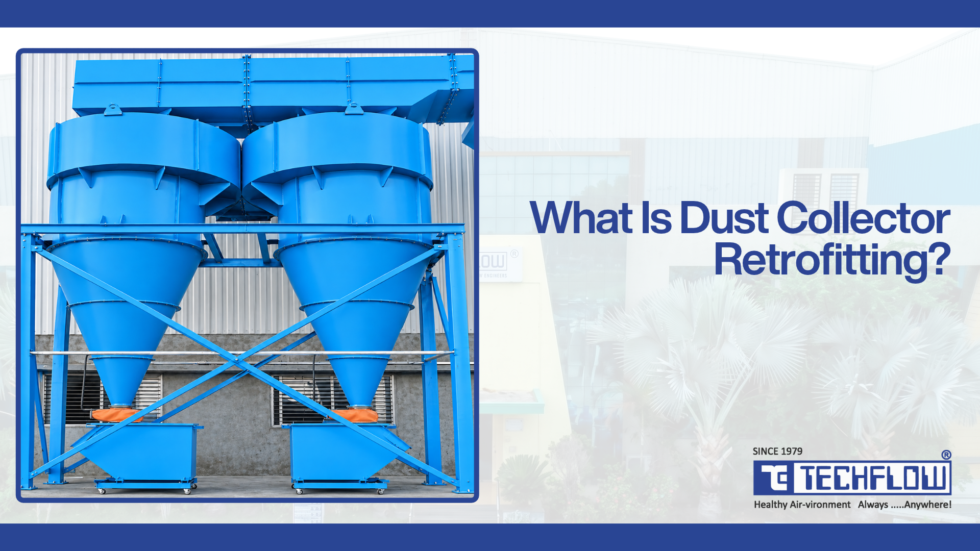
The scope can be narrow, such as a filter media change, or system-wide, covering hoods, ducts, the collector, the fan, dust discharge and controls. The collector is only one part of a ventilation system, so a retrofit looks at how every part interacts.
Retrofit, upgrade, modernisation, conversion and replacement compared
These terms are often used interchangeably, but they describe different scopes, budgets and risks.
| Term | What changes | Typical examples | What usually stays |
|---|---|---|---|
| Retrofit | Specific components replaced, added, or reconfigured to fix a defined gap | Membrane or higher-temperature media, inlet baffle, clean-on-demand control, larger or better-sealed rotary airlock | Housing, support structure, hopper, most ductwork |
| Upgrade | Capacity or capability increased beyond the original design | Added filter area or compartments, larger fan or motor, extra pickup points | Core collector and site layout |
| Modernisation | Controls, drives and monitoring brought up to current practice | ΔP transmitters, programmable cleaning controls, variable frequency drive (VFD), bag leak detection or emission monitoring | Mechanical equipment |
| Conversion | Cleaning or collection technology changed inside the existing casing | Shaker or reverse-air to pulse-jet; electrostatic precipitator (ESP) to fabric filter | Casing, foundations, part of the structure |
| Replacement | A new collector is installed | New pulse-jet bag filter sized for today's airflow and emission limit | Possibly ducts, stack and foundations |
Conversions sit closest to replacement in cost and risk. A March 2023 memo prepared by Sargent & Lundy and published by the US EPA, which reviewed particulate control upgrades at US power plants, notes that converting an ESP to a baghouse would need an extended outage and extensive casing modification. It may also need fan modifications and duct reinforcement for the higher pressure drop, and performance is limited by the air-to-cloth ratio the old casing geometry allows. The memo adds that such a conversion is unlikely to match the outlet emissions of a new stand-alone baghouse.
Signs Your Existing Dust Collector Needs An Upgrade
Some problems are maintenance, and a repair fixes them. Others are design problems that keep returning because the system is being asked to do something it was not built for.
A three-question test: maintenance issue or retrofit case?
- Does the problem return after a correct repair? A torn bag replaced and never seen again is maintenance. Bags that keep failing in the same position after cages, baffles, and blowpipes have been corrected point to a design condition, such as inlet velocity or media choice.
- Is the system running at or beyond its design point? Compare measured airflow, dust loading, gas temperature, and moisture with the original design basis. If any of them has moved materially, the collector is working outside its envelope.
- Has the requirement changed? A tighter consent limit, more pickup points, a new process stream, or higher throughput changes the duty itself. Maintenance cannot restore a margin that was never designed in.
A ‘yes’ to any of these questions justifies evaluating a retrofit, not committing to one.
Common signs and what they indicate
| Sign | Usually maintenance when… | Points toward a retrofit when… |
|---|---|---|
| High differential pressure and rising filter resistance | It follows a cleaning fault, wet compressed air, or a one-off upset, and clears after repair | It persists with a healthy cleaning system because airflow has grown, the dust has become finer, or the media cannot release the cake |
| Dust leakage and reduced filtration performance | A torn bag, poor seating, or a leaking door seal is found and fixed | Emissions stay close to the limit with intact bags, or the limit has been tightened below what the current media and air-to-cloth ratio can reliably achieve |
| Inadequate suction and inconsistent airflow | Dampers were moved, a duct is blocked, or a belt is slipping | Branches have been added since commissioning, and the fan or collector cannot supply the total airflow now required |
| Frequent filter bag failures | One installation error or one upset caused them | Failures recur after cages, baffles and blowpipes are corrected, pointing to media, temperature, chemistry or inlet design |
| Excessive compressed air consumption | Leaking diaphragms or a wrong timer setting is found | The design depends on fixed-interval cleaning, or the header and supply cannot recover between pulses at the current duty |
| Rising maintenance and operating costs | A single costly event drove the increase | Spend rises year on year on the same failure modes, and fan power climbs with pressure drop |
| Outdated cleaning controls and inefficient dust discharge | A timer card or airlock motor fails | The controls offer only fixed-interval cleaning with no ΔP feedback, or the discharge device is undersized for current dust rates |
| Increased production capacity or changed process requirements | Not applicable: this is always a design question | Always: any change in gas volume, temperature, moisture, dust load, or emission limit needs a fresh design check |
Confirm the cause before specifying any change.
Which Dust Collector Components Can Be Retrofitted?
Most components of a dust collection system can be upgraded without replacing the collector body. The table summarises the options; the sections below explain the engineering behind each.
Component upgrade options at a glance
| Component | Retrofit options | Potential benefits | Limitations and engineering checks |
|---|---|---|---|
| Filter bags and media | Different fibre for temperature or chemistry; PTFE membrane surface; anti-static, oil- and water-repellent finishes; pleated elements in place of bags | Lower emissions, better cake release, longer bag life, compliance with a tighter limit | Cannot fix an airflow or inlet design fault; media must suit the cleaning method; element length may need cage and tubesheet changes |
| Cleaning mechanism | Shaker or reverse-air to pulse-jet; new blowpipes, nozzles and venturis; larger diaphragm valves; resized headers | Higher usable air-to-cloth ratio in the same casing, more consistent cleaning | Needs a reliable compressed air supply; casing, tubesheet and clean plenum must accept the change; more flexing per bag |
| Fans, motors and air handling | Re-rated or new fan; VFD; motor upsizing; corrected inlet and outlet ducting | Restored or increased airflow; energy savings where the fan is oversized or runs at part load | Casing pressure rating, motor and electrical capacity, foundations, noise |
| Ductwork, dampers and airflow distribution | Resized branches, balancing dampers, wear-resistant bends, leak sealing, inlet baffles or diffusers | Even capture at every hood, less dust settling, less inlet abrasion on bags | Transport velocity for the dust; added resistance on the fan; combustible dust isolation requirements |
| Rotary airlocks and dust discharge | Larger or differently rotated valves, wear-resistant tips and linings, zero-speed monitoring | Reliable discharge, less air inleakage and re-entrainment | Fill efficiency, abrasion, temperature, pressure difference across the valve |
| Hoppers and material handling | Heaters and insulation, aeration pads, vibrators or shakers, level indicators, revised valley angles or liners, pneumatic conveying of collected dust | Fewer blockages, no hopper storage, less manual handling | Hopper geometry changes are structural work; dust flow properties must be known |
| Pulse-jet controls and compressed air | Programmable controllers with clean-on-demand, dedicated receivers, dryers and filters, pressure transmitters | Cleaning matched to load, lower compressed air use, better data | Control logic must be set from site data; no single cleaning mode suits every filter |
| ΔP monitoring and automation | ΔP transmitters per compartment, bag leak detection, temperature and level alarms, integration with plant SCADA or online emission monitoring | Early warning, trend-based maintenance, compliance evidence | Instruments inform decisions but fix nothing; they need calibration and probes suited to the gas |
Filter bags and filter media
Changing media is usually the least disruptive retrofit, but it is easy to get wrong. The 2023 EPA memo found that, across the power plants it reviewed, the lowest filterable particulate emissions were generally achieved with fibreglass bags carrying a PTFE membrane. It also found that committing to more frequent bag changeout may achieve significant incremental reductions.
A media change can still be expensive. EPA's Air Pollution Control Cost Manual describes pleated cartridges as a nearly direct replacement for standard bags and cages in existing baghouses, yet in one case it cites the retrofit cost as 70% as much as building a new baghouse.
TECHFLOW's filter bag media selection guide explains how gas temperature, gas chemistry, moisture and dew point, dust behaviour, the emission limit and the cleaning method narrow the choice. Specify media for the worst operating hour, not the average one.
Cleaning mechanism and pulse-jet conversion
The same EPA cost manual notes that pulse-jet baghouses run at about double the gas-to-cloth ratio of shaker or reverse-air units, and that most newly erected baghouses are pulse jets. That is why converting an older shaker or reverse-air collector to pulse-jet cleaning is a common capacity retrofit.
Feasibility depends on two things. The casing, tubesheet, and clean plenum must be able to take cages, blowpipes, and valves, and the plant must be able to supply clean, dry compressed air. TECHFLOW's pulse jet vs reverse air baghouse comparison covers the trade-offs in bag life, energy, compressed air dependence, and emissions.
Fans, motors and air handling
The US Department of Energy's fan system sourcebook explains that fan power varies with the cube of speed, so reducing speed by 20% cuts fan power by about 50%. Where an existing fan is oversized, or the load varies, a VFD may save energy. Where the fan is undersized for new branches, a re-rated impeller or a new fan is needed.
In both cases, check the collector casing's pressure rating. EPA's pulse-jet fabric filter fact sheet notes that standard fabric filters can be used in pressure or vacuum service only within about ±640 mm w.c. (25 in. w.c.). TECHFLOW manufactures low-, medium-, and high-pressure centrifugal fans and customised ID and FD fans, and its centrifugal fan selection guide covers fan types and selection in more detail.
Ductwork, dampers and airflow distribution
Ducts that suited the original layout often run too slow or too fast once branches are added. Too slow and dust settles; too fast and bends wear through. Retrofit options include resized branches, balancing dampers locked at commissioned positions, wear-resistant bends on abrasive duty, and inlet baffles or diffusers that spread gas evenly inside the collector.
Give the fan connection the same attention as the hoods. The DOE sourcebook warns that an elbow placed close to a fan outlet can create a system effect that cuts delivered flow by up to 30%.
Rotary airlock valves and dust discharge
A worn or undersized airlock lets air leak up into the hopper and limits how fast dust leaves it. TECHFLOW's rotary airlock valve guide explains that fill efficiency can range from about 40% for difficult, aerated or fine cohesive powders to roughly 90% to 95% for dense, free-flowing granules. Sizing on optimistic assumptions is a common cause of underperformance.
TECHFLOW's Roto Tuff rotary airlock valves are offered with closed, open, helical and adjustable-tip rotors, including drop-through versions for dust collection duty, with ratings up to 300°C.
Hoppers and material handling
Hopper retrofits range from heaters, insulation and flow aids to changes in geometry. TECHFLOW's components range includes aeration pads and motorised shakers for dust collectors, and its pneumatic conveying systems can move collected dust away continuously so the hopper never becomes storage. Geometry changes affect structural loads and should follow a test of the dust's flow properties.
Pulse-jet controls and compressed air
Replacing a fixed-interval timer with a programmable controller allows clean-on-demand operation tied to ΔP. The study suggests no single cleaning mode suits every filter. A full-size collector study of pleated cartridges by Lo, Chen and Pui (Powder Technology, 2010) found that clean-on-time worked better for filters with a high pleat ratio (above 4.0) and clean-on-demand worked better for a low pleat ratio (below 4.0). Tank pressure was critical to cleaning, while pulse duration had only a small effect. Downstream particle concentration during cleaning was at least twice that during filtration.
Over-cleaning therefore has an emissions cost as well as a compressed air cost. A compressed air retrofit should also secure stable header pressure, adequate receiver volume, and dry, oil-free air before anyone fine-tunes pulse settings.
Differential pressure monitoring and automation
Monitoring lets operators trend ΔP per compartment, gas temperature, hopper level, fan current and vibration, and particulate emissions. EPA's bag leak detection best practices list early warning of leaks and pending bag failures, and the ability to isolate leaks in multi-compartment baghouses, among the benefits.
In India, CPCB directed the 17 categories of highly polluting industries in 2014 to install online continuous emission monitoring systems (OCEMS). CPCB's Guidelines for Continuous Emission Monitoring Systems also caution that actual stack conditions dictate instrument suitability. Opacity monitors are not suitable where flue gas is below its dew point, and sticky, moist gas can coat probe surfaces.
How To Improve Dust Collector Performance Through Retrofitting
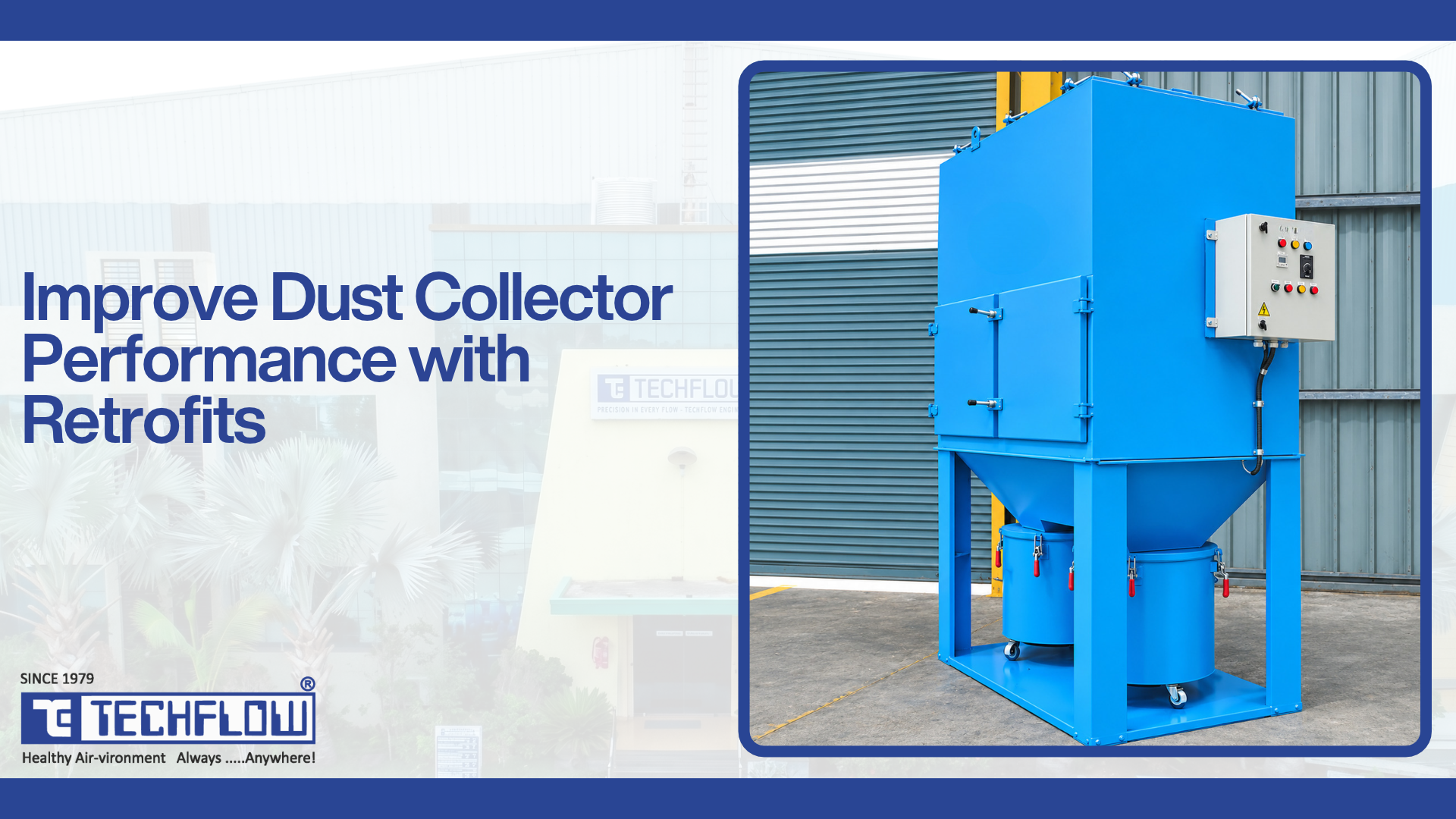
Dust collector performance improvement comes from matching each part of the system to the duty it actually sees today. Work in this order: airflow and distribution first, then media and cleaning, then controls and monitoring
Engineering modifications and how to verify them
| Objective | Engineering modification | How it can improve performance | Verify before and after |
|---|---|---|---|
| Optimise filter media for actual dust and operating conditions | Select fibre, finish and surface treatment from measured temperature (continuous and peak), moisture, acid gases and dust behaviour | Better cake release, lower residual pressure drop, lower emissions, longer bag life | Gas analysis and temperature log before; ΔP baseline, emissions and bag condition after |
| Improve cleaning sequences and compressed air delivery | Programmable controls with ΔP feedback, correct header and receiver sizing, dryers and drains, realigned blowpipes and nozzles | Steadier ΔP, less over-cleaning, lower compressed air use | Header pressure trace and pulse count before and after; compressor load hours |
| Correct fan capacity and airflow distribution | Re-rate or replace the fan, add a VFD, fix inlet and outlet system effects, add inlet baffles or diffusers in the collector | Required airflow at every hood, even loading across bags, less inlet abrasion | Pitot traverse and fan curve plot before; hood static pressures and airflow after |
| Address ductwork restrictions and leakage | Resize branches for transport velocity, seal leaks, replace worn bends, rebalance and lock dampers | Restored capture at the source, less settled dust, less wasted fan capacity | Static pressure profile at each hood, collector and fan, compared with design |
| Improve hopper geometry and dust discharge | Larger or better-sealed airlocks, flow aids, heaters and insulation, revised valley angles or liners, continuous conveying | Fewer blockages, less re-entrainment onto bags, lower fire risk from stored dust | Hopper level trend, airlock speed and current, bag bottom condition |
| Upgrade instrumentation and monitoring | ΔP transmitters per compartment, bag leak detection or emission monitoring, temperature, level and vibration sensors, data logging | Faults caught early, maintenance planned on trends, compliance evidence on record | Instrument calibration; alarm setpoints agreed against the new baseline |
Set acceptance criteria before the work starts
A retrofit without measurable targets cannot be judged. Before the design is frozen, agree to the values that define success, such as:
- Airflow at each hood
- A ΔP operating band
- An emission level with margin below the consent limit
- Compressed air use per hour
- Fan power
Measure them before the shutdown and again after commissioning, under comparable production.
What results to expect, and what not to promise
Actual results depend on how far the system had drifted from its design, the dust and gas conditions, and how well the new and old parts are integrated. The EPA memo makes the same point for particulate controls generally: costs and applicability are site- and unit-specific. Be cautious of any proposal that quotes a fixed percentage improvement before measuring your system.
Dust Collector Replacement Vs Retrofit: A Detailed Comparison
The right answer comes from comparing the existing system with the duty it must meet for the rest of its life, not just today's symptoms.
| Factor | Favours a retrofit when… | Favours replacement when… | How to assess it |
|---|---|---|---|
| Existing equipment condition | Casing, tubesheet, hopper and supports are in good condition, with corrosion limited to replaceable parts | Shell plates, tubesheet or supports are thinned, cracked or distorted; leaks recur at welds | Visual inspection, plate thickness survey, structural check of supports |
| Required filtration capacity | The target emission level is achievable with better media, cleaning or sealing at the current filter area | The target needs more filter area or a different technology than the casing can hold | Required air-to-cloth ratio for the dust and media against the area the casing can physically hold |
| Current and future airflow | Airflow growth fits within the casing at a sound air-to-cloth ratio, possibly with added compartments | Future airflow would push the air-to-cloth ratio beyond a sound value even after conversion or added area | Measured airflow plus planned expansions, against the casing's realistic maximum |
| Structural compatibility | Foundations, supports, and casing pressure rating can carry the new loads and fan suction | A larger fan, taller bags, or a heavier hopper would exceed structural or pressure limits | Load and pressure-rating check against the original design documents |
| Capital investment | Targeted changes address the limiting components | The retrofit scope approaches new-build cost, as in the cartridge case EPA cites | Costed options for both paths on the same performance basis |
| Installation complexity | Work fits inside the existing footprint and access | Extensive cutting, re-plating and restricted access make the retrofit riskier than a new build | Site survey of access, crane positions and interfaces |
| Production downtime | Work can be staged by compartment or completed within a planned shutdown | The retrofit needs a long outage, while a new unit could be built alongside and tied in during a short shutdown | Outage plan for each option, including tie-in time |
| Long-term operating requirements | The upgraded system will run within design margins for its remaining life | Energy, compressed air and maintenance costs stay high because the old design limits remain | Life-cycle cost over the planned remaining operating life |
A six-step decision framework
- Define the duty: Set today's and the planned future airflow, dust load, gas temperature and moisture, and the emission limit with a margin. Without this, no option can be judged.
- Measure the existing system: Carry out a pitot traverse, static pressure profile, ΔP trend review, gas analysis, emission review, and a structural condition survey.
- Find the limiting component: Identify whether the gap is in airflow, filter area, media, cleaning, discharge, fan, structure, or controls.
- Test the casing against the duty: If the required air-to-cloth ratio fits the filter area the casing can hold, and the structure is in good condition, a retrofit is technically feasible. If not, look at adding compartments or a parallel module. If neither is practical, evaluate replacement.
- Compare complete options on equal terms: Price each feasible path against the same acceptance criteria, including downtime, energy, and maintenance over the remaining life.
- Decide, then verify: Commission against the agreed acceptance criteria and record a new baseline.
The EPA memo adds a caution for step 4. Baghouses can be expanded with longer bags or extra compartments, but most are not designed with spare height, so expansion often means significant modification to the existing equipment.
Worked example: can the casing take more airflow?
The air-to-cloth ratio is the gas flow divided by the net filter area. The figures below are illustrative, not design values.
| Today | After a planned expansion | |
|---|---|---|
| Gas flow | 45,000 m³/h (750 m³/min) | 60,000 m³/h (1,000 m³/min) |
| Installed filter area | 500 m² | 500 m² |
| Air-to-cloth ratio | 1.5 m/min | 2.0 m/min |
Suppose 1.5 m/min is the ratio that works reliably for this dust, media, and cleaning method. Holding it at the new flow needs about 667 m² of cloth, roughly a third more than today.
The question then becomes physical. Can longer bags, an added compartment, or pleated elements add about 167 m² inside this casing, with a tubesheet, clean plenum, and supports to match? If yes, a retrofit or expansion is technically feasible. If not, a parallel module or a new collector belongs on the option list. For compartmented collectors, run the check on net area, with one compartment offline for cleaning or maintenance.
Key Factors To Evaluate Before A Dust Collection System Retrofit
Every factor below shapes what a retrofit can achieve. Most can be measured on the running plant, and measured values are more reliable than the original design assumptions.
| Factor | Why it matters for the retrofit | What to measure or obtain |
|---|---|---|
| Dust characteristics | Stickiness, abrasiveness, hygroscopic behaviour and combustibility decide media, finishes, inlet design and safety measures | Dust samples; process description; combustibility data where relevant |
| Particle size | Finer dust forms denser, higher-resistance cakes and is harder to capture, which drives media and air-to-cloth choices | Particle size distribution of inlet dust |
| Gas temperature | Sets the media shortlist and insulation needs; peaks matter as much as averages | Continuous and peak temperature log across a full operating cycle |
| Humidity and dew point | Condensation blinds media and corrodes the casing; acid gases raise the dew point | Moisture content, acid gas analysis, coldest surface temperatures |
| Gas volume and airflow | Defines the required filter area, fan duty and duct sizes, now and after planned expansion | Pitot traverse at the main duct and branches; design flows for planned additions |
| Pressure drop | Shows how much of the fan's capacity the collector consumes and how far media and cleaning have drifted | ΔP trend including post-cleaning values; static pressure profile across the system |
| Available space | Limits added compartments, longer bags, a new fan or a parallel module | Layout drawings, clearances, access for bag removal and lifting |
| Structural condition | A corroded casing or weak supports can rule out a retrofit | Plate thickness survey, inspection of welds, supports and foundations |
| Electrical requirements | Larger motors, VFDs, heaters and new instruments need supply capacity and control integration | Available electrical capacity, MCC space, control system interfaces |
| Safety | Combustible dust, confined spaces, hot surfaces and work at height all affect design and installation | Dust hazard data, site permits, existing explosion protection and isolation |
| Future production capacity | A retrofit sized only for today may need redoing within a few years | Production plans and expected process changes over the system's remaining life |
Combustible dust and safety
If the collected dust is combustible, treat the retrofit as a change to a safety-critical system. NFPA 660, Standard for Combustible Dusts and Particulate Solids, published in December 2024, consolidates NFPA 652 and five commodity- and industry-specific standards (NFPA 61, 484, 654, 655 and 664) into one document.
Changing airflow, media, filter type, ducting, or hopper arrangements can alter explosion venting, isolation and ignition control requirements. Review the dust hazard analysis (DHA) and explosion protection before the design is frozen, and specify anti-static media where the dust can hold a charge.
Dust Collector Retrofit Evaluation Checklist
Use this checklist to structure an internal review or a discussion with an engineering partner. Each item should end with a recorded value, document, or decision.
1. Define the requirement
- [ ] Current and planned airflow, by branch
- [ ] Emission limit from the current consent, with the margin you want to hold
- [ ] Production changes expected over the system's remaining life
- [ ] The problems the retrofit must solve, ranked by cost or risk
2. Collect operating data
- [ ] Pitot traverse at the main duct and key branches
- [ ] Static pressure at each hood, across the collector and at the fan inlet and outlet
- [ ] ΔP trend for at least the last few months, with post-cleaning values
- [ ] Gas temperature (continuous and peak), moisture and acid gas data
- [ ] Dust samples for particle size and behaviour; combustibility data where relevant
- [ ] Emission records and stack test reports
- [ ] Compressed air pressure, consumption and quality at the collector
- [ ] Fan speed, motor current and vibration history
3. Inspect condition
- [ ] Casing, tubesheet and hopper plate condition, including thickness where corrosion is visible
- [ ] Supports, foundations and access platforms
- [ ] Bags, cages, blowpipes, valves and venturis
- [ ] Airlock, conveyor and hopper flow aids
- [ ] Ductwork wear, leaks and settled dust
- [ ] Existing explosion protection, isolation and fire detection where dust is combustible
4. Engineering analysis
- [ ] Required filter area and air-to-cloth ratio for the duty, against what the casing can hold
- [ ] Fan curve against the new system curve, and the casing pressure rating
- [ ] Media options checked against temperature, chemistry, moisture and cleaning method
- [ ] Discharge capacity against the expected dust rate
- [ ] Electrical and control capacity for new drives, heaters and instruments
- [ ] Dust hazard analysis reviewed for the proposed changes
5. Options and decision
- [ ] Retrofit, expansion and replacement options priced on the same acceptance criteria
- [ ] Shutdown duration and tie-in plan for each option
- [ ] Life-cycle energy, compressed air and maintenance costs compared
- [ ] Acceptance criteria agreed in writing
6. Execution and verification
- [ ] Installation plan with permits, isolation, lifting and confined-space controls
- [ ] Pre-shutdown fabrication and material checks completed
- [ ] Commissioning tests against every acceptance criterion
- [ ] Operator and maintenance training on the changed system
- [ ] New baseline recorded: airflow, ΔP band, emissions, compressed air use, fan power
Industries That Often Need Dust Collector Retrofits
The industries below run hot, abrasive, high-volume, or combustible duties where collectors often drift away from their original design basis.
| Industry | Common retrofit drivers | Engineering considerations |
|---|---|---|
| Cement | Capacity increases, tighter consent limits, hot and abrasive kiln, mill and cooler gases | High-temperature media and fans, inlet abrasion, hopper flow of fine powders |
| Steel, DRI and sponge iron | Hot fume and abrasive dust, sparks, production expansion | Gas pre-cooling, spark arrestors, media for heat and abrasion |
| Foundries | Mixed metal fume and sand, variable loads, added pickup points | Spark protection, abrasion at bends and inlets, cleaning matched to load |
| Power generation and boilers | Revised particulate norms for thermal power plants, fuel changes, ESP performance shortfalls | Acid dew point and moisture, ESP upgrade versus fabric filter conversion, fan capacity for higher pressure drop |
| Mining, minerals and crushing | Abrasive dust, expanded crushing and screening circuits | Wear-resistant ducting, inlet design, robust discharge |
| Powder coating and shot blasting | Abrasive media fines, combustible powders, new booths or blast rooms | Abrasion, anti-static media, explosion protection where powders are combustible |
| Food, grain and flour | Combustible dust, hygiene requirements, capacity changes | Anti-static media, explosion protection, cleanable discharge |
For power generation in India, the 2015 amendment set particulate limits by installation date: 100 mg/Nm³ for units installed before 31 December 2003, 50 mg/Nm³ for units installed from 2003 up to 31 December 2016, and 30 mg/Nm³ for units installed from 1 January 2017. Limits for other industries vary by sector and consent, and later notifications or directions can revise them. Confirm the current notification and your consent conditions before setting a retrofit target. For a broader overview, see TECHFLOW's guide to air pollution control norms in India and other countries.
How To Choose A Dust Collector Retrofit Partner
A retrofit joins new parts to an old system, so most of the risk sits at the interfaces. The partner you choose should be able to take responsibility for the whole chain, from measurement to verified performance.
| Capability | Why it matters in a retrofit |
|---|---|
| Engineering assessment | Decisions must rest on measured airflow, pressures, gas conditions and dust properties, not on the original nameplate |
| Component compatibility | New media, cages, valves, fans and airlocks must fit the existing casing, tubesheet, pressure rating and controls |
| System design | Every change shifts the fan operating point, pressure drop and cleaning demand, so the system must be designed as a whole |
| Installation planning | Shutdown time is usually the scarcest resource; fabrication, lifting and tie-ins must be planned before the outage starts |
| Commissioning | Cleaning settings, damper positions and alarms must be set from site readings, then proven against the acceptance criteria |
| Post-installation evaluation | Performance should be measured under normal production and recorded as the new baseline |
Questions to ask before you commit
- What data will you collect on site, and what will you measure after commissioning?
- Which components are limiting performance, and how did you establish that?
- What happens to fan duty, pressure drop, and compressed air demand after the change?
- Can the casing and structure carry the new loads and suction?
- How long is the shutdown, and what can be done before it?
- How will the combustible dust hazard analysis be updated, if applicable?
- What training, spares, and support follow handover?
How Techflow Supports Retrofit And Upgrade Decisions
TECHFLOW has designed and manufactured air pollution control equipment in Ahmedabad since 1979 and has supplied more than 3,500 dust collection and air pollution control systems. Its published capabilities include:
- TECHFLOW describes starting each design with an application study covering airflow, particle size, inlet dust loading, temperature and moisture, chemical compatibility, and plant layout constraints.
- Our FAQs state that where existing equipment lacks provision for pollution control systems, TECHFLOW can modify the layout without hampering performance or production capacity.
- In-house equipment for the parts a retrofit touches. This includes pulse jet bag filters, pulse jet cartridge filters, envelope filters, reverse-air cassette filters, cyclones and multiclones, ESPs, centrifugal fans, rotary airlock valves, wear-resistant bends, aeration pads and pneumatic conveying.
- Our turnkey projects cover design, engineering, procurement, construction and commissioning, and our erection team installs systems across India and abroad.
- We train operators and maintenance staff, provide ongoing technical support, offer AMCs, and stock genuine spare parts. For its ESPs, it supports installed units with tuning and replacement parts.
Ask us for project references in your industry as part of your evaluation.
Next step: Measure before you decide
A retrofit can restore capture, steady the pressure drop, and bring emissions back within margin, often with less disruption than a new installation, provided the structure is in good condition and the limiting components have been correctly identified. If the duty has outgrown the casing, a new or additional collector is the better investment. Either way, the decision should rest on measurements of the existing system against the required duty.
Talk to TECHFLOW about your existing dust collection system. Share your process, airflow, gas conditions, emission limit, and the problems you are seeing, and TECHFLOW's engineering team will help you assess whether a retrofit, an expansion, or a new system is the right path. Contact TECHFLOW or email sales@techflow.net.
Frequently Asked Questions (FAQs)
An industrial dust collector retrofit is a planned modification that replaces, adds, or reconfigures selected parts of an existing system, such as filter media, the cleaning system, fan, ducts, dust discharge, or controls. The aim is to fix a shortfall found by measurement or meet a new requirement while the main collector body stays in service.
Common signs include differential pressure that stays high with a healthy cleaning system, emissions close to the limit with intact bags, weak suction at hoods after new branches were added, repeated bag failures in the same position, and rising compressed air use and fan power. If a fault returns after a correct repair, it usually points to a design mismatch rather than a maintenance issue.
Upgrading only the limiting components usually costs less than a new collector, but a broad retrofit can approach new-build cost. Broad retrofits can approach new-build cost: EPA's cost manual records a cartridge retrofit that cost 70 percent as much as a new baghouse. Compare both paths against the same performance targets, shutdown time, and life-cycle operating costs before deciding.
Divide the planned gas flow by the net filter area to get the new air-to-cloth ratio, then compare it with the ratio that works for your dust, media, and cleaning method. If the casing can physically hold enough extra cloth, through longer bags, added compartments, or pleated elements, an upgrade is feasible. If not, plan for a parallel module or a new collector.
Yes, if the casing, tubesheet, and clean plenum can accept cages, blowpipes, and valves, and the plant can supply clean, dry compressed air. Pulse-jet baghouses typically run at around twice the gas-to-cloth ratio of shaker or reverse-air designs, so conversion can raise capacity in the same casing.
It can, but it is a major project. Conversion needs an extended outage and extensive casing work, may require fan and ductwork changes for the higher pressure drop, and is limited by the air-to-cloth ratio the ESP casing allows. Evaluate an ESP upgrade and a new stand-alone fabric filter alongside it. TECHFLOW's guide to choosing between an ESP and a bag filter compares the two technologies.
Only if the media is the limiting factor. If airflow has grown, cleaning energy is weak, or condensation is blinding the bags, new media will blind or overload in the same way. Check airflow, compressed air pressure, gas temperature against dew point, and post-cleaning ΔP first, then choose media for the worst operating condition.
Duration depends on scope: media and control upgrades may fit within a routine shutdown, while conversions, added compartments, or fan replacements need longer outages.
Yes, if the dust is combustible. Changes to airflow, filter type, media, ducting or hoppers can alter explosion venting, isolation and ignition control needs. Review the dust hazard analysis under NFPA 660, which now consolidates NFPA's combustible dust standards in one document, before the retrofit design is finalised.
Share the process description, current and planned airflow, gas temperature and moisture, dust type and samples if available, the emission limit in your consent, recent ΔP and emission trends, drawings of the existing collector, and the problems you want to solve. With these inputs, TECHFLOW's engineers can assess whether a retrofit, an expansion, or a new system fits.


