


Key Takeaways
- A foundry dust collection system captures metal fume and particulate dust at the source, furnace, shakeout, and grinding, then filters each through technology matched to the contaminant.
- Metal fume is sub-micron and needs cartridge collectors or electrostatic precipitators; coarse sand and grinding dust are usually handled by pulse-jet baghouses.
- OSHA caps respirable crystalline silica at 50 µg/m³ over an 8-hour shift, with a 25 µg/m³ action level, and requires engineering controls before respirators.
- Indian foundry furnaces must collect fumes before stack discharge under the Environment (Protection) Rules, 1986; Delhi-NCR's 50 mg/Nm³ limit lands in 2026.
- NFPA 660, effective 6 December 2024, merged six combustible dust standards into one, reshaping how systems for aluminium and magnesium must be engineered.
- Capture-hood placement outweighs filter choice: air that escapes the hood never reaches the collector, however efficient that collector is.
- Foundry sand and heavy metal particulate need a duct transport velocity of roughly 4,000 to 4,500 fpm to stay suspended and avoid settling.
Every foundry runs on the same sequence: melt, pour, cool, shake out, finish, and every stage puts a different contaminant into the air. That single fact is why so many dust collection systems disappoint the plants that bought them:
- A collector sized beautifully for shakeout sand will lose the sub-micron fume rising off the furnace.
- A precipitator built for furnace fume will choke on the coarse abrasive load from a fettling bench.
Controlling emissions in a foundry is not one purchase. It is a sequence of engineering decisions that begins with correctly identifying what is actually airborne at each point of the process. This guide follows that sequence the way an engineer specifying a system would, from the contaminants and their sources, through why fume and dust demand different filtration and which collector fits which process, down to the unglamorous details, hood placement, duct velocity and media temperature rating, that decide whether the whole thing works.
Quick Answer: What a Foundry Dust Collection System Does
A foundry dust collection system captures airborne metal fume and particulate dust at the point of generation- furnace mouths, pouring stations, shakeout lines, and grinding or fettling booths and routes it through filtration matched to the contaminant. Fine metal fume from melting and pouring generally needs cartridge filters or electrostatic precipitators built for sub-micron particles and sustained heat, while coarser sand and casting dust is typically handled by pulse-jet baghouses.
A correctly engineered system also accounts for combustible dust risk under NFPA 660, correct duct velocities that keep particles suspended rather than settling, and filter media rated for the actual inlet temperature. Done right, it holds exposure below limits such as OSHA's silica permissible exposure limit, meets stack emission norms, and protects the people working the floor every shift.
What a Foundry Dust Collection System Is
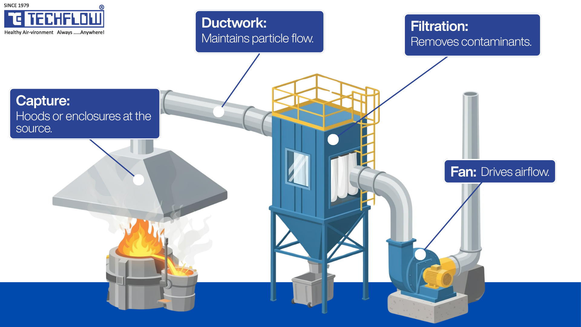
A foundry dust collection system is industrial air pollution control equipment built to capture, transport, and filter airborne contamination generated across melting, pouring, sand handling, and finishing. It has four working parts:
- Capture hoods or enclosures at the emission source.
- Ductwork sized to keep particles suspended in transit.
- A filtration stage (baghouse, cartridge collector, electrostatic precipitator or wet scrubber) that separates contaminant from air.
- A fan that drives airflow through the system.
Its job is twofold: it protects the people on the floor by holding airborne concentrations under regulatory exposure limits, and it protects equipment and product quality by removing dust before it settles on machinery, fouls sensors, or contaminates the casting process.
The distinction that matters most is that a dust collection system removes contamination at its source, unlike a general exhaust fan, which only dilutes it across a room. That source-capture logic, refined around foundry process design rather than treated as generic ventilation, is the foundation everything else rests on.
The four components at a glance
| Component | Function | Where it sits |
|---|---|---|
| Capture hood/enclosure | Pulls contaminated air away from the process before it disperses | At or immediately above the emission source |
| Ductwork | Transports captured air to the collector without particle settling | Between hood and collector |
| Filtration stage | Separates particulate or fume from air | Baghouse, cartridge, ESP, or scrubber housing |
| Fan/motor assembly | Drives airflow through the entire system | Usually after the filter, on the clean-air side |
Where Metal Fume and Particulate Dust Come From
Understanding where each contaminant originates is what makes every later decision coherent. The foundry process throws off three broad categories.
Melting and pouring: When metal is heated past its melting or boiling point, trace elements vaporise and condense in air into extremely fine solid particles, often smaller than one micron. This is the visible haze around an induction furnace or ladle even when no obvious dust is present. It is also the mechanism behind metal fume fever, a short-term flu-like illness once common enough among foundry workers to be nicknamed "foundry fever," most often tied to overexposure to zinc oxide fume. Zinc, cadmium, iron and aluminium oxides are the metals most commonly involved.
Shakeout, sand handling and reclamation: Separating the casting from its sand mould throws coarser, heavier particulate into the air: silica sand dust and core binder residue. Mulling, mixing and conveying add continuous, moderate-volume dust of mixed particle size. This is the category respirable crystalline silica falls under, and it is one of the most heavily regulated particulates in the industry.
Grinding, fettling and finishing: Removing flash and gates through grinding, cutting or shot blasting generates metal grinding dust and abrasive residue, coarse to fine, and sometimes sparks, a detail that matters the moment combustible metals are involved.
| Process stage | Primary contaminant | Typical particle behaviour |
|---|---|---|
| Melting (induction, cupola, arc furnace) | Metal fume (zinc, manganese, iron oxides) | Sub-micron, rises with the heat plume |
| Pouring and cooling | Metal fume, smoke from mould binders | Fine particulate combined with combustion gases |
| Shakeout and sand reclamation | Silica sand dust, core binder residue | Coarser, heavier, settles faster |
| Sand mulling, mixing, conveying | Fine sand and additive dust | Mixed particle size, high volume |
| Grinding, fettling, cutting, shot blasting | Metal grinding dust, abrasive residue | Coarse to fine, can include combustible fines |
Metal Fume vs Particulate Dust: Why the Difference Changes Your Filter
On the shop floor, "dust" and "fume" get used interchangeably. For filtration design, they describe genuinely different problems, and confusing them is the single most common reason a system underperforms:
- Metal fume is sub-micron, penetrates deep into the lungs, and is hard for coarse media to catch, so fume-heavy zones need cartridge or electrostatic technology, not a baghouse sized for sand.
- Particulate dust from shakeout and grinding is coarser and heavier, settles faster, and is generally well handled by fabric filtration.
A system built to control one will not adequately control the other. This is not a preference; it is a consequence of how the two contaminants form and behave.
| Attribute | Metal fume | Particulate dust |
|---|---|---|
| Formation mechanism | Vaporisation and condensation | Mechanical disturbance |
| Typical particle size | Sub-micron | Micron to several hundred microns |
| Primary source processes | Melting, pouring, welding | Shakeout, sand handling, grinding |
| Health concern | Deep lung penetration, metal fume fever | Silicosis, respiratory irritation |
| Best-suited filtration | Cartridge, electrostatic precipitator | Baghouse |
Most real foundry layouts therefore run two or three collector types in parallel rather than routing every process into a single central unit. Combining a furnace fume stream and a shakeout dust stream into one collector usually means over-engineering for the worst case of both instead of optimising for either. Separating fume-generating processes from dust-generating processes at the design stage is the first thing an experienced specifier checks.
Ferrous vs Nonferrous Foundries: Different Dust, Different Rules
Treating a steel foundry and an aluminium foundry as interchangeable when specifying dust collection is a common and costly mistake, because their risk profiles diverge at the level of chemistry.
Ferrous foundries (iron and steel) deal primarily with silica sand dust, iron oxide fume and coarser grinding dust. Explosion risk is generally lower than in nonferrous operations, but silica exposure control tends to dominate the compliance conversation, since sand-heavy moulding and shakeout are central to ferrous casting.
Nonferrous foundries (aluminium, magnesium, zinc) face a materially different hazard: fine metal dust from these processes is combustible and, under some conditions, explosible. This is precisely the risk the combustible dust standards were written to address, and it changes the design brief substantially. Features that a ferrous-only design would never need become mandatory:
- Spark-resistant fan construction.
- Explosion venting or isolation on ductwork.
- Grounding and bonding throughout the system to prevent static ignition.
| Factor | Ferrous foundries | Nonferrous foundries (Al / Mg) |
|---|---|---|
| Dominant contaminant | Silica sand dust, iron oxide fume | Fine combustible metal dust |
| Primary regulatory concern | Silica exposure compliance | Combustible dust and explosion protection (NFPA 660) |
| Typical collector risk features | Standard fabric or cartridge filtration | Explosion venting, spark-resistant fans, grounding and bonding |
| Housekeeping sensitivity | Moderate | High: dust accumulation is itself a hazard |
Why It Matters: Health, Compliance and Cost
OSHA silica exposure limits
The most consequential number for any foundry handling silica sand is OSHA's permissible exposure limit for respirable crystalline silica. Under 29 CFR 1910.1053, the limits are fixed:
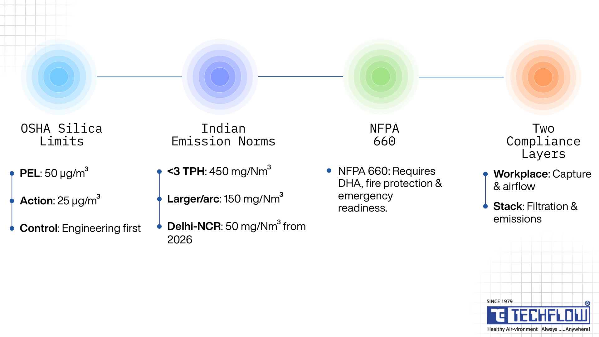
- Permissible exposure limit (PEL): 50 µg/m³, calculated as an 8-hour time-weighted average.
- Action level: 25 µg/m³ as an 8-hour TWA, which triggers exposure monitoring and medical surveillance.
Foundries are named directly among the industries most affected, alongside abrasive blasting, mining, and stone fabrication. Crucially, OSHA requires the hierarchy of controls: where feasible engineering and work-practice controls are not sufficient to reach or fall below the PEL, the employer must still use them to cut exposure to the lowest feasible level and only then supplement with respiratory protection. Engineering controls come first, and a dust collection system is exactly that.
Indian emission norms: CPCB and the Environment (Protection) Rules
For foundries operating in India, the governing framework is different but no less binding. Under Schedule VI of the Environment (Protection) Rules, 1986, foundry furnaces carry explicit particulate matter obligations:
- Cupolas below 3 tonne/hour melting rate: within 450 mg/Nm³.
- Cupolas of 3 tonne/hour and above, and arc furnaces of all sizes: within 150 mg/Nm³.
- Arc and induction furnaces: fumes must be collected before emissions are discharged through the stack.
These norms are enforced by the Central Pollution Control Board (CPCB) and the State Pollution Control Boards under the Air (Prevention and Control of Pollution) Act, 1981.
The bar is tightening. Through Statutory Direction No. 98, the Commission for Air Quality Management (CAQM) set a uniform 50 mg/Nm³ particulate limit for metal industries operating furnaces in Delhi-NCR, effective from 1 August 2026 for large and medium industries and 1 October 2026 for the remainder. Any foundry specifying a system today, particularly across the NCR districts of Delhi, Ghaziabad, Noida, Faridabad and Gurugram, should design for the stricter number, not the one it can just scrape past now.
That these limits are achievable with the right equipment is well established. A peer-reviewed study of iron foundries in Tamil Nadu found that a cartridge filter fitted to an induction furnace reduced suspended particulate matter to less than 20 mg/Nm³, the best efficiency among the pollution control devices surveyed. TECHFLOW's own primary fume extraction systems for induction furnaces are engineered to push outlet emissions as low as 2 mg/Nm³, depending on the applicable local norms, comfortably inside even the 2026 Delhi-NCR standard.
NFPA 660 and combustible metal dust
Fine combustible metal particulate suspended in ductwork or a collector housing, with an ignition source present, can flash or explode, and combustible metals burn faster and generate higher peak pressures than most other combustible dusts.
With an effective date of 6 December 2024, NFPA 660 consolidated the six commodity-specific combustible dust standards, NFPA 61, 484, 652, 654, 655 and 664, into a single comprehensive standard. Two of them, NFPA 484 (Combustible Metals) and NFPA 652 (Fundamentals of Combustible Dust), are the ones most relevant to a nonferrous foundry. For a plant handling aluminium or magnesium, the standard now requires:
- A documented Dust Hazard Analysis (DHA), kept current as the process changes.
- Emergency preparedness built in: plans for dust-related fires and deflagrations, coordination with responders, and employees trained to act.
Indoor air quality vs stack emissions: two separate layers
It is easy to think of dust collection as one compliance problem. It is really two, and a system can pass one while failing the other.
- Indoor and workplace exposure is about what the people on the floor breathe. It is governed by exposure limits such as OSHA's PEL or the equivalent workplace standards, measured at the worker's breathing zone, and addressed primarily through hood design and airflow.
- Stack and outdoor emissions are about what leaves the building through the collector's exhaust. It is governed by CPCB or local pollution board limits in mg/Nm³ and addressed primarily through filtration efficiency at the collector.
A system can capture contamination well at the hood, protecting workers, yet use an undersized or poorly maintained filter that lets too much through the stack, failing emissions compliance, or the reverse. Specifying and maintaining a system means accounting for both layers, not just the one that is easier to measure.
The hidden cost of doing nothing
Uncontrolled dust does not stay a compliance issue; it becomes an operating cost:
- It accelerates wear on bearings, motors, and electrical panels.
- It drives absenteeism and turnover on a floor that is already hard to staff.
- When an inspection does come, the penalty is rarely a one-time fine. It is more often mandated downtime while the facility retrofits the system it should have installed in the first place.
Core Collector Technologies Foundries Use
Baghouse (fabric filter) systems
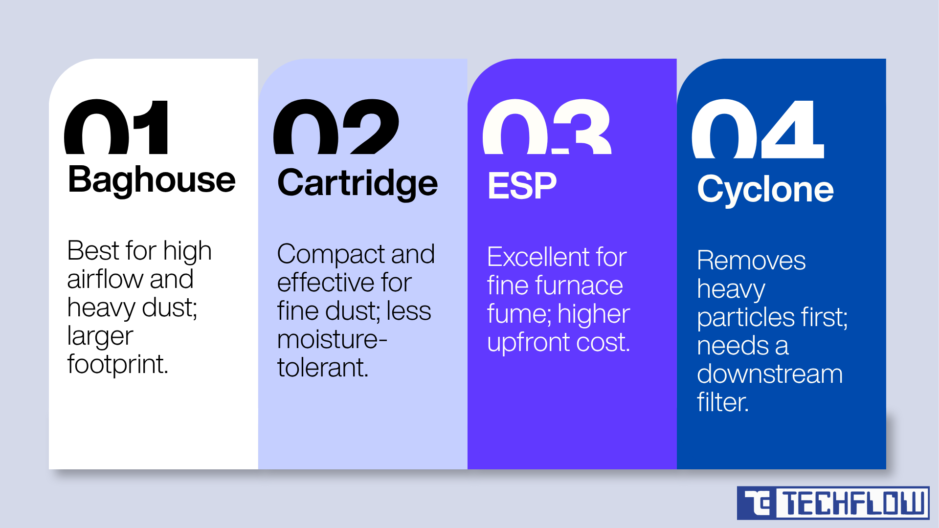
Air is pulled through long fabric bags, typically six to eight inches in diameter, cleaned periodically with a pulse of compressed air. Baghouses remain the standard choice for high air volume and coarser dust loading, exactly the profile of shakeout and sand handling exhaust.
- Strengths: handles volume and heavy loading efficiently; relatively low operating cost per unit of airflow; widely available replacement parts.
- Limitations: bag life drops sharply above the media temperature rating; moisture can cake dust onto bags and blind them; larger footprint than cartridge units.
Cartridge filter collectors
Pleated media in a compact cylinder gives far more filtration surface per unit of footprint than a baghouse, making cartridge collectors a strong fit for fine metal fume or fine sand dust near grinding and fettling stations.
- Strengths: compact footprint for the surface area delivered; strong on fine particulate; easier to retrofit into tight spaces.
- Limitations: less tolerant of moisture or sticky dust than a baghouse; media selection matters more here than with any other technology; higher replacement cost per unit.
Electrostatic precipitators (ESP)
An ESP charges particles electrically and collects them on oppositely charged plates, which suits the extremely fine, sub-micron fume from furnace mouths and pouring.
- Strengths: excellent on sub-micron fume; low pressure drop; runs continuously without periodic bag or cartridge changes.
- Limitations: higher upfront cost; depends on consistent voltage and clean plates; less forgiving of sudden particulate spikes.
In practice, an ESP at the furnace typically sits downstream of a primary cyclone and a cooling stage that brings exhaust temperature down before it reaches the plates, protecting both the precipitator and its efficiency.
Cyclone pre-separators
Cyclones use centrifugal force to drop out the heaviest particles before air reaches a finer downstream collector, extending that collector's filter life.
- Strengths: little maintenance, no moving parts or media to replace; reduces load on downstream filtration; protects high-temperature streams as a first stage.
- Limitations: rarely meets emission limits alone; ineffective on very fine sub-micron particulate; pre-treatment only, not a standalone solution.
Matching technology to process
| Process | Best-suited technology | Why |
|---|---|---|
| Induction/arc furnace melting | ESP or high-temperature cartridge collector | Sub-micron fume, sustained high heat |
| Pouring and cooling | ESP, or cartridge with cyclone pre-separator | Fine fume mixed with combustion byproducts |
| Sand shakeout and reclamation | Pulse-jet baghouse | High volume, coarser mixed particle sizes |
| Sand mulling and conveying | Baghouse or cartridge, by fineness | Continuous, moderate-temperature dust |
| Grinding, fettling, cutting | Cartridge collector | Compact footprint, fine metal grinding dust |
| Shot blasting | Cyclone plus cartridge or baghouse | Coarse abrasive fines plus fine dust |
Getting the Engineering Right
Capture hood design
Where air is pulled from matters more than any other single variable in system performance. A canopy hood over a furnace mouth, or a side-draft hood at a grinding bench, captures contamination before it disperses into the shop. A room-exhaust fan trying to clean already-dispersed air needs dramatically more airflow to achieve the same result, and often still falls short.
Common hood types by application:
- Canopy hoods positioned above the source, where hot contaminants naturally rise (furnace mouths, ladles).
- Side-draft hoods beside the source, where cross-drafts or operator access rule out a canopy (grinding benches).
- Enclosing hoods that surround the process almost entirely, where the highest capture efficiency is required (shot blast cabinets).
- Downdraft tables that pull contaminants away from the operator's breathing zone, common at fettling stations.
This is especially sensitive around an induction furnace melt shop, where the natural rise of a hot fume plume makes hood positioning even more critical than in cooler processes.
Duct transport velocity
Ductwork has to move air fast enough to keep particles suspended rather than settling at elbows and vertical risers. The authoritative reference is the American Conference of Governmental Industrial Hygienists (ACGIH) Industrial Ventilation manual, which sets transport velocity by material rather than a single blanket number; heavier materials need higher velocities to stay airborne. Foundry sand and heavy metal particulate typically require a minimum transport velocity of 4,000 to 4,500 fpm in horizontal ductwork.
Fall below that minimum, and the outcome depends on the dust:
- Inert dust: particulate settles inside the duct, restricting airflow, a maintenance problem.
- Combustible metal dust: the same settling becomes a fire and explosion hazard.
These are general design guidelines, not a substitute for application-specific engineering calculations.
Filter media and temperature rating
Standard polyester media degrades quickly near furnace-adjacent heat. Higher-temperature options cost more upfront but avoid the repeated premature failure that standard media suffers in these zones. Selecting media rated for the actual measured inlet temperature, including the peak during pouring, is the single most reliable way to avoid the most common cause of premature filter failure.
| Media type | Approx. max continuous temperature | Best suited for |
|---|---|---|
| Standard polyester | ~135°C | Sand handling, shakeout, cooler processes |
| Aramid (Nomex-type) | ~200°C | Moderate-heat fume near melting and pouring |
| PTFE-treated / membrane | ~260°C | Fine, sticky or corrosive particulate |
| Fibreglass | ~260°C and above | Highest continuous-heat furnace-adjacent zones |
Common Mistakes When Specifying a System
Even well-intentioned upgrades go wrong in predictable ways. The recurring ones are worth naming so they can be caught early:
- Sizing the collector to the process's average load instead of its peak, when pouring and shakeout spike well above average.
- Treating hood design as an afterthought to the collector purchase, when the collector is only as good as the air it actually receives.
- Ignoring inlet temperature when selecting media, the leading cause of premature failure near furnaces.
- Routing a combustible metal dust stream into a system with no explosion protection, a shortcut that becomes a serious safety gap the moment aluminium or magnesium fines are involved.
- Sizing ductwork by convenience of layout instead of calculated velocity, which leads to settling and blockages.
- Deferring maintenance until a visible problem appears, by which point the system has usually been underperforming for weeks.
Installation and Maintenance: Protecting Uptime
A maintenance rhythm that holds up looks roughly like this:
- Each shift: check pressure gauges against baseline; listen for unusual fan noise.
- Weekly: inspect pulse-jet solenoids and cleaning cycles; check hopper levels.
- Monthly: spot-check duct velocity at key branches; inspect ductwork joints for leaks.
- Quarterly: inspect filter media wear; check fan bearings and belts; verify ESP plate voltage where applicable.
- Annually: run a full performance test against the original design airflow; review hood positioning against any process layout changes.
The early warning signs are worth reading correctly, because most of them point upstream of the filter:
- Persistent haze near the furnace or grinding station signals a hood capture or airflow balance problem, not a filter problem.
- Pressure drop climbing without recovery after a cleaning cycle means media is at end of life, or load has exceeded the original sizing.
- Visible dust settling inside ductwork means duct velocity has dropped below the material's minimum transport speed.
- Dust on machinery farther from the source means hoods are not sized or positioned for the real contamination pattern.
- An unexplained rise in fan motor amperage often points to a partially blocked filter or a developing duct restriction.
Measuring the Return on the Investment
The business case is easiest to justify across three separate columns rather than one blended figure.
| Dimension | What it captures | Typical payback signal |
|---|---|---|
| Compliance cost avoidance | Avoided fines and mandated shutdowns | Immediate, but hard to quantify until an inspection happens |
| Health and workforce cost | Lower absenteeism, reduced turnover | Visible within 6 to 18 months |
| Production cost | Less downtime, longer equipment life, less rework | Usually the largest line item over 2 to 3 years |
Wide price variation between quotes for a seemingly similar system usually comes down to a handful of factors:
- Airflow volume required, driven by the number and size of hoods rather than the collector alone.
- Filtration technology chosen, since ESPs and high-temperature cartridge systems cost more than a comparable baghouse.
- Explosion protection for combustible nonferrous dust.
- Ductwork complexity, where longer runs and more elbows raise material and installation cost.
- Ongoing consumables, which differ meaningfully across baghouse, cartridge, and ESP over a system's life.
Foundries that evaluate on installed cost alone tend to undersize. The ones that check the business case against the downtime and rework figures already sitting in their own maintenance logs usually land on a more accurate, and often larger, justified budget.
A Practical Selection Checklist
Before specifying a system, work through these questions:
- Have you separated fume-generating processes (melting, pouring) from dust-generating processes (shakeout, grinding) rather than routing both into one collector?
- If the foundry processes aluminium, magnesium, or other combustible metals, does the system include explosion protection consistent with NFPA 660?
- Has hood placement been reviewed for each source point rather than assumed from a generic layout?
- Has duct velocity been calculated per material transported rather than taken from a default?
- Is filter media rated for the actual measured inlet temperature at each collector, including peak pouring conditions?
- Does the maintenance plan include both a shift or weekly checklist and a deeper quarterly inspection?
- Have you accounted for both indoor exposure limits and stack emission limits as separate requirements?
- Has the system been sized for peak contaminant generation rather than average load?
Why TECHFLOW Is the Foundry Dust Collection Partner to Specify
A collector installed somewhere on the floor does not solve the problem. Metal fume, respirable silica, and combustible metal dust each demand a different capture point, a different filtration approach, and, for reactive metals, a different safety standard. A system built for one contaminant but quietly expected to handle all three is where compliance gaps and near-misses come from. Closing that gap is what TECHFLOW has built its foundry practice around.
TECHFLOW Enterprises Pvt. Ltd. is a Gujarat-based manufacturer of air pollution control systems that has been designing, manufacturing, and installing dust collection and furnace fume extraction equipment for foundry and steel plants for over four decades, from a 150,000 sq. ft. facility in Ahmedabad. That is the difference between buying a box and buying a system engineered around your process.
What sets TECHFLOW apart for foundries:
- Every capture point, one engineered system: Furnace fume extraction, grinding and fettling booths, shakeout, sand handling, and finishing are designed to work together, not bolted on as separate purchases that fight each other for airflow.
- Proven emission performance: TECHFLOW's primary and secondary fume extraction systems for induction furnaces route fume through cooling and high-efficiency filtration to reach outlet emissions as low as 2 mg/Nm³, comfortably inside CPCB norms and the tightened 50 mg/Nm³ Delhi-NCR standard.
- The right technology for each contaminant. Pulse-jet and cartridge dust collectors, baghouses, electrostatic precipitators.
- Purpose-built finishing capture. Grinding and fettling booths with integrated dust collectors use a louvred-baffle enclosure that breaks the dust velocity and draws it into the collector, paired with motorised-shaker or pulse-jet units to suit the application.
- Airflow engineered in-house. High-efficiency centrifugal fans and blowers are built for the high-volume, high-temperature duty of foundry extraction, so the fan is sized to the system rather than approximated, the single most common cause of underperformance.
- Domestic delivery, global reach. TECHFLOW supplies foundries across India and exports worldwide, with installation and after-sales support behind every system.
For a foundry weighing a new system or a retrofit, this is the practical advantage: one partner who understands the difference between a shakeout line and a furnace mouth, and engineers for both. Explore TECHFLOW's foundry solutions to see the full range in context.
Conclusion
Controlling metal fume and particulate emissions in a foundry is not a single-equipment decision. It starts with correctly identifying what is in the air at each stage, because fume and dust behave, and must be filtered, differently. Getting the stakes right- the exposure limits, the combustible dust risk under NFPA 660, the CPCB emission norms, and the real production cost of ignoring all three- turns compliance from a checkbox into a business case.
From there, the engineering is a matter of matching collector to process instead of forcing one system to do every job, and getting the unglamorous details right: hood placement, duct velocity, media rated for actual heat, and a budget built around peak load. None of it holds without a maintenance rhythm behind it. A foundry that treats its dust collection system as production infrastructure, backed by engineering built around the process rather than a generic box, ends up with fewer shutdowns, a safer floor, and a far easier conversation the next time an inspector walks in.
Specify the right foundry dust collection system, the first time.
Metal fume, respirable silica, and combustible metal dust each need a different capture point and a different filter, and getting that mix wrong is where compliance gaps and downtime begin. TECHFLOW engineers dust collection and furnace fume extraction systems built specifically for foundry floors, from grinding and fettling booths to induction furnace fume extraction that meets CPCB norms.
Talk to a TECHFLOW engineer about a system matched to your melt shop, shakeout line, and finishing bays. Explore TECHFLOW's foundry solutions →
Frequently Asked Questions (FAQs)
Metal fume forms when metal vaporises at high heat and condenses into extremely fine, sub-micron particles, typically during melting and pouring. Dust is coarser solid particulate disturbed mechanically, such as sand dust from shakeout or metal particles from grinding. Fume needs finer filtration, such as cartridge collectors or electrostatic precipitators, while coarser dust is often well handled by baghouses.
OSHA's permissible exposure limit for respirable crystalline silica is 50 µg/m³ as an 8-hour time-weighted average, with an action level of 25 µg/m³ that triggers monitoring and medical surveillance. It applies to general industry, including foundries. Employers over the limit must implement engineering controls first, using respiratory protection only where controls alone cannot close the gap.
Under the Environment (Protection) Rules, 1986, arc furnaces and cupolas of 3 tonnes per hour and above are held to 150 mg/Nm³ for particulate matter, smaller cupolas to 450 mg/Nm³, and induction and arc furnaces must collect fumes before discharge through the stack. A stricter 50 mg/Nm³ standard for metal industries with furnaces in Delhi-NCR takes effect in 2026.
Electrostatic precipitators and high-temperature cartridge collectors are generally best suited to induction furnace fume, because the fume is extremely fine and the exhaust runs at sustained elevated temperatures that standard fabric media cannot tolerate long-term. The precipitator or cartridge usually sits downstream of a cyclone and a cooling stage.
Technically yes, but rarely efficiently. Sand dust and metal fume differ enough in particle size and temperature that combining both streams into one baghouse usually means over-engineering the system for the worst case of each rather than optimising for either. Most foundries run separate collectors for fume and dust.
NFPA 660 is a standard effective 6 December 2024 that consolidated six earlier combustible dust standards, including NFPA 484 (Combustible Metals) and NFPA 652 (Fundamentals of Combustible Dust), into one document. It matters most for nonferrous foundries processing aluminium, magnesium, or similar reactive metals, setting requirements for a Dust Hazard Analysis, explosion protection, and written emergency response planning.
Transport velocity is the minimum speed needed to keep a specific material suspended and moving toward the collector. Foundry sand and heavy metal particulate typically need 4,000 to 4,500 fpm. If velocity drops below the minimum, particulate settles inside the duct, restricting airflow, and for combustible metal dust, it creates an added fire and explosion hazard.
The most common causes sit upstream of the filter: poorly positioned or undersized capture hoods, duct velocity too low to keep particulate moving, and airflow imbalance across branches. A hood placed against the natural rise of a hot fume plume lets contamination escape into the shop before the system can pull it in, and no downstream filter can capture what never entered the ductwork.
Replacement intervals depend on media type, inlet temperature, and dust load. A rising pressure drop that does not recover after a cleaning cycle is the most reliable field indicator that media has reached end of life, more dependable than a fixed calendar interval.
A cyclone removes the heaviest, coarsest particulate before it reaches the main filter, extending the life of downstream baghouse bags, cartridges, or ESP plates. It is a pre-treatment stage, effective on heavy particles but not on very fine sub-micron fume, and rarely meets emission limits on its own.


