


Key Takeaways
- A flue gas cleaning system (FGCS) is an integrated train of equipment that removes several pollutant families: particulate matter, acid gases (SO₂, SO₃, HCl, HF), oxides of nitrogen (NOx), heavy metals such as mercury, and dioxins/furans from combustion or process exhaust before it reaches the stack.
- FGD (flue gas desulfurization) is one stage inside an FGCS, not a synonym for it. FGD removes sulfur dioxide specifically; a full FGCS also handles dust, other acid gases, NOx, and micro-pollutants.
- There are three core acid-gas approaches: wet, semi-dry, and dry. Wet scrubbing delivers the highest removal but uses the most water and produces wastewater; semi-dry (spray dry absorption) is effectively zero-liquid-discharge; dry sorbent injection is the simplest and most compact but consumes more reagent.
- Particulate control uses a fabric (bag) filter or an electrostatic precipitator (ESP). In dry and semi-dry systems, the filter is not just a dust catcher; the filter cake is where much of the acid-gas reaction is completed.
- NOx is handled separately by SNCR (reagent injected into the furnace) or SCR (a catalyst stage); mercury and dioxins are captured by activated carbon injection, typically ahead of the bag filter.
- You select an FGCS from the gas, not from the equipment. Characterise flow, temperature, and inlet pollutant loads first; only then match technology to your emission limits, water availability, residue handling, footprint, and budget.
- In India, waste-to-energy and industrial incineration plants must meet CPCB emission standards and run OCEMS (online continuous emission monitoring), which reports SO₂, NOx, PM, CO, HCl, HF, and dioxin/furan data to regulators, so monitoring is part of the system design, not an afterthought.
Everything that leaves your stack is a matter of public record. With continuous emission monitors feeding data straight to the regulator, there is no longer such a thing as a good day for a stack test; the numbers stream around the clock, and your flue gas cleaning system (FGCS) is what keeps them where they need to be.
That single shift, from periodic testing to continuous, transmitted monitoring, has changed how this equipment should be specified. An FGCS is no longer a box you bolt on at the end of a project to clear a one-time compliance check. It is core plant infrastructure that runs every hour your process runs, and getting the configuration wrong is the kind of mistake you only discover after commissioning, when it is expensive to fix.
This guide is written for the people who own that decision: plant heads, EHS and environment managers, project and procurement engineers, and consultants specifying air pollution control for new builds and retrofits. It covers what an FGCS actually removes, how each cleaning technology works down to the reaction chemistry, the emission limits you are designing against, and a practical framework for matching a system to your gas rather than to a sales brochure.
At TechFlow, we have engineered air pollution control equipment in India since 1974, from electrostatic precipitators and bag filters to complete flue gas cleaning trains for waste-to-energy and heavy industry. What follows reflects how our engineering team approaches selection on real projects, not a textbook summary.
What Is a Flue Gas Cleaning System?
A flue gas cleaning system is the sequence of equipment that treats exhaust gas from a combustion or high-temperature process so the gas leaving the stack meets legal emission limits. "Flue gas" is simply what you get when you burn fuel or waste: a hot stream carrying dust, acidic gases, and trace toxic compounds that would otherwise enter the air.
The word to hold onto is sequence. An FGCS is rarely one machine. It is a train of stages, each targeting a different family of pollutants, arranged in a deliberate order along the duct between the process and the stack. Change the order or unbalance the stages and the whole train underperforms, even if every individual component is sound.
FGCS vs FGD: the distinction that prevents specification errors
These two terms get used interchangeably, and that loose usage causes real scoping mistakes.
- FGCS (Flue Gas Cleaning System) is the umbrella for the complete pollution-control train.
- FGD (Flue Gas Desulfurization) is one function within it: removing sulfur dioxide (SO₂).
If a supplier quotes "an FGD system" and your emissions inventory also includes hydrogen chloride, mercury, and dioxins, you have not been offered a complete solution; you have been offered one stage of it. A properly scoped FGCS addresses every regulated pollutant in your specific gas stream. The first question on any serious project is therefore not "wet or dry?" but "what exactly is in the gas, and what does it have to read at the stack?"
A Short Glossary
- FGCS: Flue Gas Cleaning System; the complete multi-stage pollution-control train.
- FGD: Flue Gas Desulfurization; the SO₂-removal function within an FGCS.
- DSI: Dry Sorbent Injection; dry powdered reagent injected into the duct.
- SDA: Spray Dry Absorption; the semi-dry route using an evaporating lime slurry.
- SNCR / SCR: Selective Non-Catalytic / Catalytic Reduction; the two NOx-control routes.
- ACI: Activated Carbon Injection; captures mercury and dioxins.
- ESP: Electrostatic Precipitator; particulate collection by electrostatic charging.
- NSR: Normalised Stoichiometric Ratio; reagent injected relative to the theoretical minimum.
- OCEMS / CEMS: (Online) Continuous Emission Monitoring System.
- ZLD: Zero Liquid Discharge; no wastewater stream leaves the process.
- TEQ: Toxic Equivalent; the basis for expressing dioxin/furan limits.
Why Flue Gas Cleaning Matters More Than Ever
Two pressures are tightening together: regulation and public scrutiny. On the regulatory side, India's framework has moved decisively toward continuous, transmitted compliance. Waste-to-energy and incineration plants are required to install Online Continuous Emission Monitoring Systems (OCEMS) that track particulate matter, NOx, SO₂, carbon monoxide, HCl, HF, and dioxins/furans and send that data in real time to the Central Pollution Control Board (CPCB) and state boards.
In January 2026, the Ministry of Environment, Forest and Climate Change notified the Solid Waste Management Rules, 2026, effective 1 April 2026, superseding the 2016 rules with a stronger, digital-first compliance architecture while retaining waste-to-energy as a permitted processing pathway subject to CPCB emission standards.
The practical consequence is simple to state and hard to overstate: emissions are now visible and continuous. An FGCS that could squeak through an annual test but drift out of limits between tests is no longer fit for purpose. The system has to hold its numbers reliably, every shift, for the life of the plant, which raises the bar on control, instrumentation, and the engineering margin built into the design.
For waste-to-energy, cement, steel, foundry, and mineral processing, the FGCS has stopped being a peripheral utility. It now determines whether a plant can legally operate at all.
The Emission Limits You Are Actually Designing Against
You cannot size a cleaning train without a target. In India, the CPCB stack standards for municipal solid waste incineration set the outlet limits that a waste-to-energy FGCS must meet. The table below lists the widely referenced values and their averaging periods. Always confirm the current, project-specific limits with CPCB and your state board, since standards and consent conditions evolve, but this is the shape of what you are engineering toward.
| Pollutant | Limit | Basis/averaging period |
|---|---|---|
| Particulate matter (PM) | 50 mg/Nm³ | Half-hourly average |
| Hydrogen chloride (HCl) | 50 mg/Nm³ | Half-hourly average |
| Sulfur dioxide (SO₂) | 200 mg/Nm³ | Half-hourly average |
| Oxides of nitrogen (NOx, as NO₂) | 400 mg/Nm³ | Half-hourly average |
| Carbon monoxide (CO) | 100 mg/Nm³ (½-hr) / 50 mg/Nm³ (daily) | As noted |
| Hydrogen fluoride (HF) | 4 mg/Nm³ | Half-hourly average |
| Total organic carbon (TOC) | 20 mg/Nm³ | Half-hourly average |
| Total dioxins and furans | 0.1 ng TEQ/Nm³ | 6–8 hour sampling |
| Cadmium + thallium (Cd+Tl) | 0.05 mg/Nm³ | Sampling window |
| Mercury (Hg) | 0.05 mg/Nm³ | Sampling window |
Values are corrected to a reference oxygen level (11% O₂) and normalised to standard temperature and pressure on a dry basis. Two design implications fall straight out of this table:
- Dioxins and furans at 0.1 ng TEQ/Nm³ is an extremely low limit. It is met not by one device but by a combination of good combustion, rapid gas quenching, and activated carbon capture on the filter; more on this below.
- The half-hourly basis punishes variability. A system that meets the limit on average but spikes during load swings will still fail. That is why inlet load variability, not just the average, drives the design.
For plants and groups benchmarking against international practice, the European Union's Industrial Emissions Directive and its associated BAT reference documents represent a stricter reference point and are worth understanding for future-proofing, even where they do not directly apply.
What Pollutants Does a Flue Gas Cleaning System Remove?
Different fuels and processes produce different pollutant mixes, and a well-designed FGCS is built around the contaminants in your gas. The common targets and their control stages:
| Pollutant | What it is | Typical control stage |
|---|---|---|
| Particulate matter (dust/fly ash) | Fine solid particles carried in the gas | Bag filter or ESP |
| Sulfur dioxide (SO₂) / sulfur trioxide (SO₃) | Acid gases from sulfur in fuel; drive acid rain and corrosion | FGD: wet, semi-dry, or dry |
| Hydrogen chloride (HCl) & hydrogen fluoride (HF) | Acid gases, prominent in waste and RDF combustion | Acid-gas scrubbing/sorbent injection |
| Oxides of nitrogen (NOx) | Formed at high combustion temperatures | SNCR or SCR |
| Heavy metals (mercury, cadmium, lead, etc.) | Volatile toxic metals | Activated carbon injection + filtration |
| Dioxins & furans (PCDD/PCDF) | Trace persistent organic pollutants | Combustion control + gas quenching + activated carbon |
| Carbon monoxide / TOC | Products of incomplete combustion | Combustion optimization |
The operative point: you cannot specify an FGCS without first knowing your pollutant inventory. A cement kiln, an RDF-fired waste-to-energy boiler, and a steel-plant furnace produce genuinely different gas streams and need genuinely different trains.
The Chemistry Behind Acid-Gas Removal
Most of the "which type?" decision comes down to how acid gases are neutralised, so it helps to see what is actually happening. Acid-gas cleaning is, at its core, an acid–base reaction between the acidic pollutants and an alkaline reagent. The two common reagents are hydrated lime (calcium hydroxide, Ca(OH)₂) and sodium bicarbonate (NaHCO₃).
With hydrated lime:
- SO₂ + Ca(OH)₂ → CaSO₃ + H₂O (calcium sulfite; oxidises to gypsum, CaSO₄, in wet systems)
- 2 HCl + Ca(OH)₂ → CaCl₂ + 2 H₂O
- 2 HF + Ca(OH)₂ → CaF₂ + 2 H₂O
With sodium bicarbonate:
This first "activates" thermally into a porous, high-surface-area sodium carbonate as it heats in the duct:
- 2 NaHCO₃ → Na₂CO₃ + H₂O + CO₂ (activation)
- Na₂CO₃ + SO₂ + ½O₂ → Na₂SO₄ + CO₂
- NaHCO₃ + HCl → NaCl + H₂O + CO₂
Why the choice of reagent matters in practice:
- Lime is inexpensive and widely available, but its reactivity depends heavily on how close the gas is brought to its water dew point; the wetter and cooler the gas (within limits), the better lime performs. It is the workhorse of wet and semi-dry systems.
- Sodium bicarbonate is more reactive and works well across a wider, higher temperature window, which makes it attractive for dry injection where the gas is not humidified. It typically costs more per tonne, and its reaction products are water-soluble salts, which affects how the residue must be handled.
The efficiency of any of these reactions is expressed as the normalised stoichiometric ratio (NSR): how much reagent you inject relative to the theoretical minimum. Wet systems approach the theoretical minimum most closely; dry injection runs at a higher NSR, meaning more reagent per unit of acid gas removed and therefore more residue to dispose of. That single parameter explains most of the operating-cost gap between the technologies.
How a Flue Gas Cleaning System Works, Stage by Stage
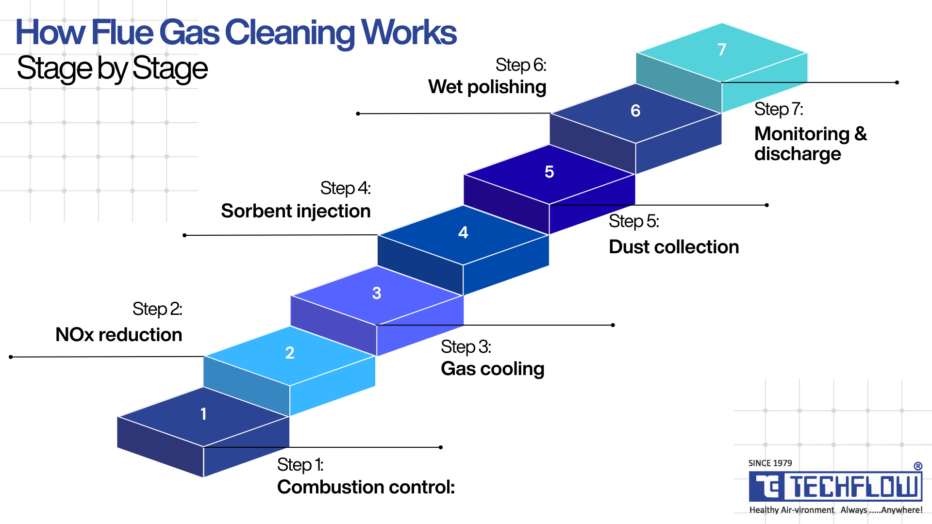
Here is how the stages fit together in a representative waste-to-energy or industrial cleaning train. Not every plant needs every stage; the value is in seeing the logic of the sequence.
1. Combustion controls the first cleaning stage
Clean stacks begin in the furnace. Complete combustion is governed by the "three T's": Temperature, Time, and Turbulence, with the gas typically held above 850 °C for at least two seconds with good mixing and adequate excess air. This destroys organics, minimises carbon monoxide, and suppresses the initial formation of dioxins. Get this stage wrong, and every downstream device spends the rest of the train cleaning up an avoidable mess.
2. NOx reduction: SNCR or SCR
- SNCR (Selective Non-Catalytic Reduction): a reagent, urea or aqueous ammonia, is injected into the hot furnace zone, roughly 850–1050 °C, where it reduces NOx to nitrogen and water without a catalyst. Lower capital cost; the design challenge is placing injection in the right temperature window and controlling ammonia slip (unreacted ammonia carried downstream).
- SCR (Selective Catalytic Reduction): the gas passes over a catalyst that drives the same reaction at lower temperature with higher, more stable NOx removal. Higher capital cost, and the catalyst is a consumable, but it is the route to the deepest NOx reductions.
3. Gas cooling and heat recovery
The gas is brought to the correct temperature window for the downstream reagents and filter media and, critically for dioxins, it is quenched rapidly through the reformation window (roughly 200–400 °C) to limit de novo synthesis, where dioxins re-form on fly-ash surfaces in the cooler post-combustion zone. Where it makes economic sense, this heat is recovered rather than dumped, sometimes via a flue gas condenser downstream.
4. Reagent and sorbent injection
This is where acid gases and micro-pollutants are captured:
- Alkaline sorbent (hydrated lime or sodium bicarbonate) is injected to neutralise SO₂, HCl, and HF per the chemistry above.
- Activated carbon is injected to adsorb mercury and dioxins. This is the stage that turns a 0.1 ng TEQ/Nm³ dioxin limit from daunting into routine: activated carbon injection followed by a bag filter is a well-documented route to dioxin removal efficiencies above 99%.
5. Particulate collection: the bag filter (or ESP)
The gas passes through the primary dust-collection device, which does two jobs at once. It captures fly ash and the spent sorbent and carbon; and because a filter cake builds on the bags, a significant share of the acid-gas reaction is completed right there on the filter surface, as gas percolates through a bed of fresh and partially reacted reagent. This is why, in dry and semi-dry systems, the fabric filter is the true workhorse of the train rather than a passive dust trap.
6. Optional wet scrubbing/polishing
Where limits are exceptionally tight, or SO₂/HCl loads are high and variable, a wet scrubber can be added as a final polishing stage to guarantee the outlet numbers.
7. ID fan and stack with OCEMS
An induced-draft (ID) fan draws the treated gas through the train to the stack, where continuous monitors verify every regulated pollutant against its limit and transmit the data to the authorities.
The engineering point: an FGCS is a system, and the stages interact. Over-dosing sorbent to chase one number can blind the filter bags, drive up differential pressure, and increase fan power and reagent cost all at once. The difference between a train that quietly complies and one that fights you every shift is the balance between the stages, not the spec sheet of any single component.
Types of Flue Gas Cleaning Systems
The defining choice is how you remove acid gases, because it shapes water use, residue, footprint, and cost more than anything else. There are three families.
1. Wet Flue Gas Cleaning (Wet Scrubbing / Wet FGD)
A liquid, typically a limestone or lime slurry, is sprayed into the gas. Acid gases dissolve into and react with the alkaline liquid, and dust is washed out simultaneously.
- Strengths: the highest removal efficiency (SO₂ removal above 90%, and often well beyond, is well established), and strong tolerance of high, variable acid loads. Wet limestone systems can produce gypsum as a saleable by-product.
- Trade-offs: the highest water consumption; a wastewater stream that must be treated; the largest equipment footprint; and downstream concerns: a saturated "wet" gas can cause corrosion and a visible plume unless managed with reheat or appropriate materials.
- Best when: SO₂/HCl loads are high, limits are very tight, and reliable water supply plus wastewater treatment are available.
2. Semi-Dry Flue Gas Cleaning (Spray Dry Absorption, SDA)
An atomised lime slurry is sprayed into the gas in a carefully controlled quantity so that all the water evaporates, leaving the reaction products as a dry powder collected downstream on the filter. The key control parameter is the approach to saturation temperature: how close the gas is brought to its water dew point, which sets both reagent efficiency and the guarantee that the residue leaves dry.
- Strengths: effectively zero-liquid-discharge (ZLD) with no wastewater to treat; efficiency close to wet in many applications; dry residue that is far easier to handle than slurry; and operation above the acid dew point, which sidesteps wet-stack corrosion and plume.
- Trade-offs: slightly lower peak efficiency than wet, and a genuine need for tight control of slurry rate and gas temperature to keep the approach in the right band.
- Best when: you want strong acid-gas removal without a wastewater stream, a very common sweet spot for waste-to-energy plants.
3. Dry Sorbent Injection (DSI / Dry FGD)
A dry powdered sorbent, such as hydrated lime or sodium bicarbonate, is injected straight into the duct. It reacts with acid gases in flight and finishes reacting in the filter cake; spent sorbent is captured on the bag filter.
- Strengths: the simplest and most compact option; the lowest capital cost; no slurry and no wastewater; the easiest to retrofit into an existing plant; and modular, quick to adjust to changing loads.
- Trade-offs: a higher normalised stoichiometric ratio means you consume more reagent per unit of acid gas, which means more residue to dispose of and, generally, a better fit for low-to-moderate acid loads than for the heaviest duties.
- Best when: footprint or water is limited, loads are moderate, or you need a fast, cost-effective retrofit to meet tightening limits.
The supporting technologies (used across all three)
- Particulate control: a bag filter (fabric filter) for very high fine-dust collection efficiency, or an electrostatic precipitator (ESP) for very large gas volumes and high temperatures.
- NOx control: SNCR (economical) or SCR (deepest reduction).
- Mercury and dioxin control: activated carbon injection ahead of the filter.
Bag Filter vs Electrostatic Precipitator: The Particulate Decision
Because the particulate device is where dry and semi-dry chemistry is completed, its selection deserves its own attention rather than being treated as a commodity.
Fabric (bag) filters capture dust by passing gas through a woven or felted media; the growing dust cake actually improves collection down to very fine particles, and periodic pulse-jet cleaning knocks the cake off into a hopper. Their strengths are extremely high collection efficiency on fine particulate and the reactive filter-cake effect that boosts acid-gas capture. The design levers are air-to-cloth ratio (filtration velocity lower is gentler and more efficient), differential pressure (which sets fan power and signals bag condition), and media selection matched to temperature and chemistry: PTFE membranes, polyphenylene sulfide (PPS), polyimide (P84), and PTFE-finished fibreglass are common choices in acidic, high-temperature waste-to-energy service.
Electrostatic precipitators charge particles in an electric field and collect them on grounded plates. Their strengths are very low pressure drop (and therefore lower fan energy) and excellent handling of very high gas volumes and temperatures, which is why they remain common on large cement and power applications. They are sized by specific collection area and the number of electrical fields. The trade-off is that they are less effective on the very finest fractions than a membrane bag filter, and they do not provide the filter-cake reaction bonus.
In modern waste-to-energy trains, the bag filter usually wins because it delivers both the fine-particulate capture and the acid-gas/dioxin reaction surface in one device. On very high-volume, high-temperature duties, the ESP still earns its place. The honest answer, again, is that the gas and the duty decide.
Wet vs Semi-Dry vs Dry: A Side-by-Side Comparison
| Factor | Wet (Wet Scrubbing) | Semi-Dry (SDA) | Dry (DSI) |
|---|---|---|---|
| Acid-gas removal efficiency | Highest | High | Moderate–high |
| Water use | High | Low | Minimal |
| Wastewater generated | Yes (needs treatment) | No (ZLD) | No |
| Residue | Slurry/gypsum (can be saleable) | Dry powder | Dry powder (higher volume) |
| Reagent efficiency (NSR) | Best | High | Lower (more reagent used) |
| Footprint | Largest | Moderate | Smallest |
| Capital cost | Highest | Moderate | Lowest |
| Operating cost driver | Water + wastewater | Reagent + control | Reagent + residue disposal |
| Retrofit friendliness | Hardest | Moderate | Easiest |
| Typical fit | High/variable loads, very tight limits | WtE, ZLD-driven sites | Compact/retrofit, moderate loads |
There is no universal winner. The right system is the one that matches your gas, your limits, and your site constraints, which is exactly what the next section is for.
How to Choose the Right Flue Gas Cleaning System
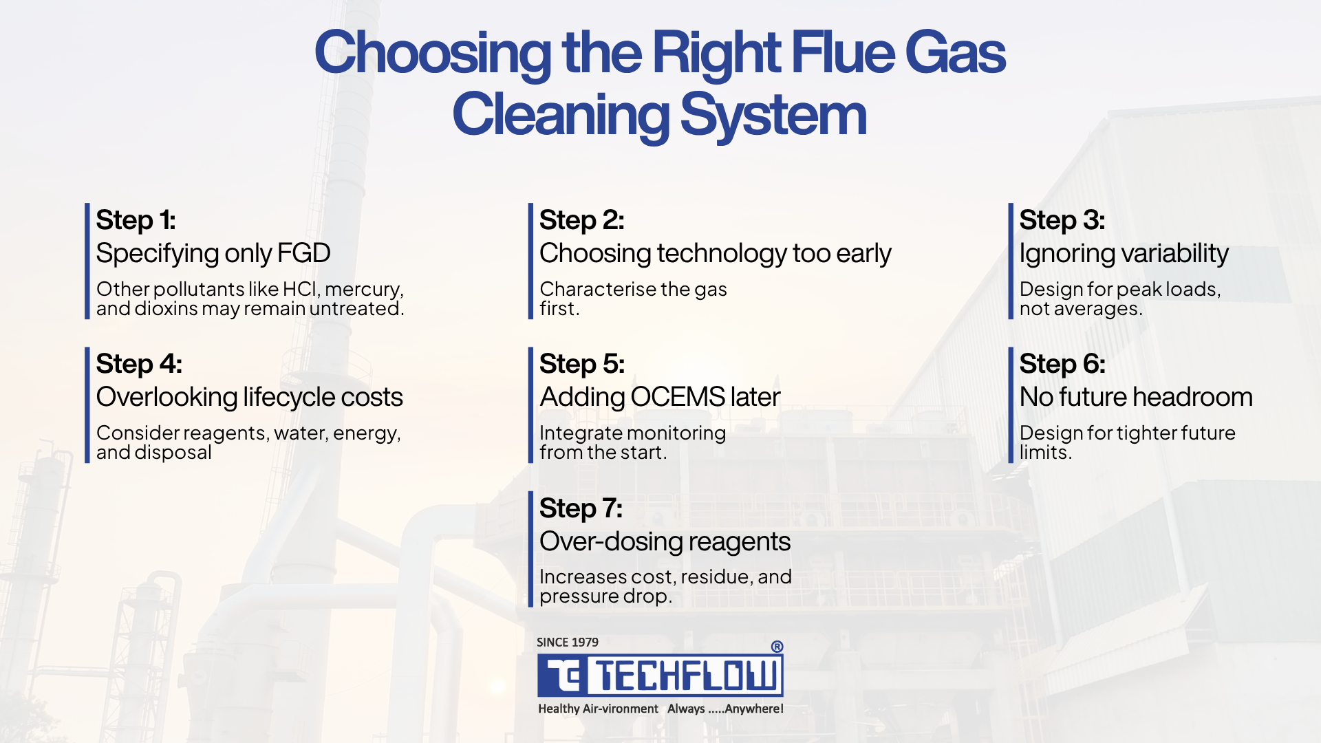
The most common and most expensive mistake is starting the conversation at "wet or dry?" That sequence is backwards. You choose an FGCS from the gas and the compliance target, then let the technology follow. Here is the order our engineers actually work in.
Step 1: Characterise the flue gas
Before anything else, establish:
- Volumetric flow rate (Nm³/h) at operating and peak conditions
- Temperature, moisture, and acid dew point
- Inlet pollutant loads: SO₂, HCl, HF, particulate, mercury, NOx and their variability, not just their averages
- Whether the source is a steady process or a fluctuating waste feed
Everything downstream depends on these numbers. A train sized for the wrong flow or the wrong inlet load will never behave, no matter how good the components are.
Step 2: Fix your compliance target
Your outlet emission limits the CPCB/SPCB values, and your specific consent conditions set the removal efficiency each stage must deliver. This, more than anything, is what separates a wet solution from a dry one for the same gas.
Step 3: Match the acid-gas technology
Weigh the comparison table against your realities:
- High, variable acid load + very tight limits → lean wet.
- Need zero-liquid-discharge, no wastewater stream → lean semi-dry.
- Limited footprint or water, moderate load, retrofit → lean dry (DSI).
Step 4: Add the pollutant-specific stages
Layer in NOx control (SNCR vs SCR based on the depth of reduction required) and activated carbon injection if mercury or dioxins are in your inventory. If those pollutants are in your profile, design them in now; retrofitting them later almost always costs more than including them from the start.
Step 5 Plan residue, water, and monitoring together
- Residue: can you sell gypsum, or must you landfill dry salts? Water-soluble sodium salts and calcium salts have different disposal profiles. This shapes operating cost every single day.
- Water: wet systems need a reliable supply and wastewater treatment; dry and semi-dry largely sidestep both.
- Monitoring: design OCEMS integration from the beginning. In India it is a compliance requirement, not an optional extra, and retrofitting sampling points and analysers into a finished plant is painful.
Step 6: Engineer for total cost of ownership, not sticker price
The cheapest system to buy is frequently the most expensive to run. Reagent consumption (driven by NSR), residue disposal, water and wastewater, and fan energy (driven by pressure drop) usually dwarf the capital difference over a plant's life. Model the whole life cost, not just the purchase order.
Step 7: Build in headroom for the future
Emission norms only tighten, as the progression of India's particulate limit from 150 to 100 to 50 mg/Nm³ illustrates. Modular, expandable designs let you add capacity or stages later without redesigning the plant. Headroom is cheaper to design in than to retrofit.
A quick reality check: if a proposal does not begin by asking for your gas data and your emission limits, it is not engineering a solution; it is selling a product. The gas comes first, every time.
Industry Applications
The right configuration is industry-specific because the pollutant mix is. TechFlow engineers flue gas cleaning and broader air pollution control across a wide spread of sectors, each with its own signature:
- Waste-to-Energy (WtE) and RDF plants: the most complex duty, combining acid gases, dioxins, mercury, and variable loads; typically semi-dry or dry trains with activated carbon injection and bag filtration, plus SNCR for NOx.
- Cement plants and kilns have very high gas volumes and dust loads, where robust particulate control is paramount.
- Steel mills, foundries, and DRI plants have furnace fume and particulate-heavy streams with process-specific gas swings.
- Mineral, crushing, and ceramic industries: abrasive, high-dust duties that punish under-specified media and ducting.
- Boilers and process furnaces across pharma, food, and allied manufacturing, where reliability and compliance sit alongside product-quality considerations.
Because TechFlow designs, engineers, and manufactures the full range in-house from electrostatic precipitators and bag filters to centrifugal fans, ID fans, and integrated flue gas cleaning systems, the stages can be matched and balanced as one coherent system rather than stitched together from parts that were never meant to work as a train.
Common Mistakes to Avoid
Drawn from real projects, these are the errors that cost plants the most:
- Specifying "FGD" when the job needed a full FGCS: SO₂ is covered while HCl, mercury, or dioxins are quietly left unaddressed.
- Choosing technology before characterising the gas: The gas dictates the solution, not the other way around.
- Designing to averages, not to variability: Waste feeds swing; a system tuned only for mean conditions fails on the half-hourly basis at the peaks.
- Ignoring residue and water economics: The lowest capital cost can hide the highest lifetime cost once reagent, disposal, and wastewater are counted.
- Treating OCEMS as an afterthought: Continuous monitoring is central to compliance now; sampling points, analysers, and data handling belong in the original design.
- Skipping future headroom: Limits only tighten. A rigid design becomes a liability the day the norms move.
- Over-dosing reagent to force a number: It masks a control problem, blinds the bags, and raises pressure drop, reagent cost, and residue all at once.
Maintenance, Monitoring, and Lifecycle
An FGCS is a system you operate, not merely install, and long-term compliance rests on a handful of fundamentals.
Keep the filter bags healthy by trending differential pressure and cleaning-cycle behaviour, and replace media on a planned basis rather than after a failure; a burst bag is both an emission event and an unplanned outage. Calibrate reagent dosing to the real, measured acid load instead of running a comfortable excess; feedback control tied to the analysers keeps NSR (and cost) where it should be. Maintain fans, dampers, and expansion joints, since leaks and drift quietly erode performance. And keep the monitoring instruments calibrated and validated, because in a continuously reported regime your data is only as trustworthy as your CEMS. A well-balanced system makes all of this routine; a poorly matched one turns basic maintenance into a permanent firefight.
Ready to Specify the Right System for Your Plant?
Every plant's flue gas is different, and the right FGCS is the one engineered around your gas, your emission limits, and your site. TechFlow has designed and manufactured air pollution control systems in India since 1974, with in-house engineering across electrostatic precipitators, bag filters, fans, and complete flue gas cleaning trains for waste-to-energy and heavy industry.
Share your flue gas data and compliance targets with our engineering team, and we'll help you scope the right configuration sized for the gas, built for the limits you actually have to meet. Contact TechFlow →
Frequently Asked Questions (FAQs)
FGCS (flue gas cleaning system) is the complete pollution-control train that removes all regulated pollutants: dust, acid gases, NOx, heavy metals, and dioxins. FGD (flue gas desulfurization) is a single stage within it, dedicated to removing sulfur dioxide (SO₂). Every FGD is part of an FGCS, but an FGCS does much more than FGD alone.
For acid-gas removal, the three families are wet (liquid scrubbing: highest efficiency, uses water, produces wastewater), semi-dry/spray-dry absorption (an evaporating slurry that leaves a dry residue, effectively zero-liquid-discharge), and dry sorbent injection (dry powder injected into the duct, simplest and most compact, but uses more reagent).
There is no single best system. The right choice depends on your flue gas flow and temperature, inlet pollutant loads and their variability, target emission limits, water availability, residue handling, footprint, and total cost of ownership. You select from the gas and the compliance target, not from an equipment preference.
A complete FGCS removes particulate matter (dust and fly ash), acid gases (SO₂, SO₃, HCl, HF), oxides of nitrogen (NOx), heavy metals such as mercury, and dioxins and furans, along with products of incomplete combustion like carbon monoxide and total organic carbon.
Yes. Under CPCB emission standards, waste-to-energy plants must control stack emissions and run online continuous emission monitoring systems (OCEMS) that transmit pollutant data to regulators in real time, which requires a properly engineered FGCS. The Solid Waste Management Rules, 2026 (effective 1 April 2026) retain waste-to-energy as a permitted pathway subject to these controls.
Through a combination of good combustion (high temperature, sufficient residence time, turbulence), rapid quenching of the gas through the reformation window to limit de novo synthesis, and activated carbon injection ahead of the bag filter. Activated carbon injection followed by fabric filtration is a well-documented route to dioxin removal efficiencies above 99%.
Dry and semi-dry systems use far less water than wet FGD. Semi-dry (spray dry absorption) evaporates all the water it uses, making it effectively zero-liquid-discharge, while dry sorbent injection uses almost none. Wet FGD uses the most water and generates wastewater that must be treated.
Yes. Dry sorbent injection is the most retrofit-friendly option because it is compact and needs no slurry or wastewater infrastructure. Semi-dry systems and additional stages such as SNCR or activated carbon injection can also be retrofitted; wet systems are the hardest to add because of their footprint and water and wastewater requirements.
A bag filter delivers very high collection efficiency on fine particulate and provides a reactive filter cake that completes acid-gas capture two jobs in one device, which is why it is common in waste-to-energy. An ESP offers very low pressure drop and handles extremely high gas volumes and temperatures, which keeps it relevant on large cement and power duties. The correct choice depends on gas volume, temperature, particulate fineness, and whether filter-cake reaction is needed.


