


Key Takeaways
- A DRI plant needs two independent systems, not one. A primary gas-cleaning train on the kiln waste gas, and a secondary de-dusting network across eight to ten material-handling points. Plants that invest only in the first one fail their fugitive emission checks.
- The national stack limit for coal-based sponge iron plants is 100 mg/Nm³ particulate matter, notified under G.S.R. 414(E) dated 30 May 2008. Gas-based plants are held to 50 mg/Nm³. Several State Pollution Control Boards prescribe stricter limits; 50 mg/Nm³ is now common in consent conditions.
- The kiln waste gas train is a sequence, not a device: dust settling chamber → after-burning chamber → waste heat recovery boiler (or evaporative cooler) → ESP or bag filter → ID fan → stack.
- Gas temperature control is the single most consequential design variable. Too hot and you destroy filter bags; too cold and you condense acid onto them or blind them. The window between the two is narrower than most specifications admit.
- Continuous emission monitoring is no longer optional. Iron and steel sit among the 17 highly polluting categories required to install online continuous emission monitoring systems (OCEMS) and transmit data in real time to CPCB and the concerned SPCB.
- The dust is worth money. Published characterisation of ESP dust from a coal-based DRI plant in Hospet, Karnataka, found roughly 14% carbon and 19% iron. Treating it as waste is a design failure as much as an environmental one.
You learn more about a coal-based sponge iron plant's air pollution control system at 2 a.m. than from any commissioning report. In daylight, with the ESP energised and the bag filters pulsing, most plants look compliant. The honest test is what the stack looks like on the night shift, during a kiln upset, or in the ninety seconds after a power dip when the emergency cap lifts.
That gap between a system that is installed and a system that actually holds its emission limit across every hour of the year is what this guide is about.
India is the world's largest producer of direct reduced iron, and the overwhelming majority of it comes from coal-fired rotary kilns rather than gas-based shaft furnaces. That single fact defines the dust problem. A kiln burning non-coking coal with 20% ash, tumbling calibrated iron ore for seven to eight hours, and discharging product at around 1,000 °C generates a waste gas stream and a set of material-handling points that will defeat an under-designed control system very quickly.
This guide covers the full picture: where the dust actually comes from, what Indian law requires, how the gas-cleaning train is put together, how to choose between an ESP and a bag filter, how to control the fugitive emissions that ruin most compliance records, and what separates a system that lasts fifteen years from one that becomes a liability in three.
What Is An Air Pollution Control System In A DRI Plant?
An air pollution control (APC) system in a DRI plant is the integrated set of equipment that captures, cools, cleans, and safely discharges every dust- and gas-bearing stream the plant produces from the rotary kiln's high-temperature waste gas down to the fine dust lifted off a product conveyor transfer chute.
In practice, it has two halves that are usually specified, budgeted and audited separately:
- The primary gas-cleaning train: This handles the kiln waste gas, the largest, hottest, dirtiest single stream in the plant. It typically comprises a dust settling chamber (DSC), an after-burning chamber (ABC), a waste heat recovery boiler (WHRB) or evaporative cooling system, a final collector (electrostatic precipitator or pulse-jet bag filter), an induced draught fan and a stack.
- The secondary de-dusting system (DDS or DE system): This is a distributed network of hoods, ducts, filters and fans covering coal and iron ore crushing, screening, transfer points, the kiln feed, cooler discharge, magnetic separation, intermediate bins, product screening and bagging, and char handling.
Both are regulated. Both are inspected. A plant can hold 45 mg/Nm³ on its main stack and still receive a closure direction because the product house is visibly emitting.
Why DRI Plants Are One Of India's Harder Dust-Control Problems
The process, in the terms that matter for dust
Coal-based direct reduction converts iron oxide to metallic iron below the fusion temperature of iron: no melting, no coking coal. Iron ore (typically calibrated 5–20 mm, 65% Fe minimum), non-coking coal and dolomite are charged into a refractory-lined rotary kiln inclined at about 2.5° and rotating between roughly 0.2 and 1.0 rpm. Material travels through the kiln in about seven to eight hours.
The kiln divides into a pre-heating zone, occupying roughly 40–50% of its length, where moisture is driven off and coal volatiles release and burn in the 600–800 °C band; and a reduction zone held at 1,000–1,100 °C, where carbon monoxide generated from the coal reduces iron oxide to metallic iron. Gas and solids move counter-current, so the waste gas leaves the feed end carrying everything the bed has shed along the way.
Product discharges at around 1,000 °C into an indirectly water-cooled rotary cooler, exits near 100 °C, and is screened and magnetically separated into DRI, char and non-magnetic fines.
Four features of this process create the dust load:
| Process feature | Consequence for the APC system |
|---|---|
| Solid fuel fired directly into a tumbling bed | Coal ash, char and ore fines are continuously entrained into the gas stream |
| Counter-current gas flow over a rotating bed | High dust carry-over compared with a static reactor |
| Kiln exit gas at roughly 850–900 °C | No filter medium survives this; the train must cool before it cleans |
| Unburnt CO and carbon leaving the kiln | Combustible content in the gas is a real ignition and deflagration hazard downstream |
The solid waste tells you the dust story
Reference figures compiled for CPCB by MECON and reproduced in the Centre for Science and Environment's 2011 sector study give a useful order of magnitude for what an APC system on a small kiln actually has to handle, per tonne of sponge iron produced:
| Waste stream | Approx. generation (t per t DRI, 0.033 MTPA plant) |
|---|---|
| Char | 0.28 – 0.30 |
| Dust from settling chamber | 0.03 – 0.04 |
| ESP dust | 0.10 – 0.13 |
| Kiln accretion | 0.02 – 0.04 |
Source: MECON data reproduced in CSE, “Sponge Iron Industry: The Regulatory Challenge” (2011). Figures are indicative reference values from that period, not a design basis; always size from your own kiln's mass balance.
The ESP figure is the one to sit with. On a 100 TPD kiln, an ESP collecting at the lower end of that band is discharging on the order of ten tonnes of dust a day. That dust has to go somewhere, through hoppers, rotary airlock valves and a conveying system that is part of the APC scope and is very often the first thing to fail.
The Regulatory Framework In India
Statutory emission and effluent standards
Sponge iron is classified under the Red category of industries, the highest pollution-potential tier. Standards specific to the sector were notified by the Ministry of Environment and Forests under G.S.R. 414(E), dated 30 May 2008, which replaced the earlier 150 mg/Nm³ stack standard with a tighter figure applied irrespective of plant size.
| Parameter | Standard | Notes |
|---|---|---|
| Stack PM: coal-based plants | 100 mg/Nm³ | Applies regardless of plant capacity |
| Stack PM: gas-based plants | 50 mg/Nm³ | |
| Carbon monoxide | Not to exceed 1% by volume | |
| Fugitive PM: within premises existing plants | 3,000 µg/m³ | Measured at 10 m from specified locations |
| Fugitive PM: within premises new plants | 2,000 µg/m³ | Measured at 10 m from specified locations |
| Minimum stack height | 30 m | Scales upward with SO₂ emission rate (below) |
| Effluent pH | 5.5 – 9.0 | |
| Effluent TSS | 100 mg/l | |
| Effluent oil and grease | 10 mg/l | |
| Effluent COD | 250 mg/l |
Source: G.S.R. 414(E), 30 May 2008, as tabulated in CSE (2011).
Stack height is tied to sulphur dioxide load, which in turn follows the sulphur content of the coal:
| SO₂ emission (kg/hr) | Minimum stack height (m) |
|---|---|
| 12.7 | 30 |
| 33.1 | 40 |
| 69.6 | 50 |
| 127.8 | 60 |
| 213.6 | 70 |
Fugitive emissions must be monitored at defined locations rather than at a single fence-line point:
| Area | Monitoring locations |
|---|---|
| Raw material handling | Wagon tippler, screen area, transfer points, stock bin area |
| Crusher | Crushing plant, vibrating screen, transfer points |
| Raw material feed | Feeder and mixing areas, transfer points |
| Cooler discharge | Discharge area, transfer points |
| Product processing | Intermediate stock bin, screening plant, magnetic separation unit, transfer points, discharge area, product separation area, bagging area |
Critical caveat: the national standard is a floor, not a ceiling
This is where plants get caught. The 100 mg/Nm³ figure is the minimum national standard. State Pollution Control Boards routinely impose stricter limits in the Consent to Operate, and environmental clearance conditions frequently specify 50 mg/Nm³ for DE system stacks and, in newer clearances, tighter values still on the main kiln stack.
A 2025 CPCB enforcement action against an iron and steel unit in Koppal district, Karnataka, illustrates the exposure precisely. The reported WHRB stack PM value was 102 mg/Nm³ above the 50 mg/Nm³ prescribed by the state board and above the 100 mg/Nm³ national minimum. The notice also flagged the absence of an access point for manual sampling in the common stack, and open storage of coal and iron ore pellets. Three separate failure modes, one visit.
Design implication: never size a final collector to the national standard. Size it to the strictest number that could plausibly appear in your consent renewal over the equipment's life, with margin. Retrofitting an extra ESP field or adding filter area later costs multiples of specifying it correctly at the outset.
CREP guidelines
Beyond the notified standards sits the Charter on Corporate Responsibility for Environmental Protection (CREP), a set of sector guidelines. For sponge iron, these are advisory rather than statutory, but they are frequently written into consent conditions, which converts them into binding obligations. The substantive points:
- ESPs and other pollution control equipment must be installed to meet the prescribed standards, and must be provided with a continuous power supply.
- An interlocking system should link plant operation to APC operation; feed conveyors stop automatically if the kiln safety cap opens or the APC system is not running.
- Fugitive emission measurement on an eight-hourly basis using a high-volume sampler.
- Plants above 0.033 MTPA should install a waste heat recovery boiler; those at 0.066 MTPA and above should install a fluidised bed combustion boiler so char can be burnt for power rather than dumped.
- Each kiln to have a separate stack.
- No new plant to be commissioned without proper pollution control equipment in place.
- Siting: at least 1 km from residential habitation and ecologically sensitive areas; at least 0.5 km from national and state highways; 5 km radial separation between plants of 0.165 MTPA and above; a 15 m green belt.
The interlocking requirement is the one worth taking seriously even where it is not mandated. It converts an APC system from something an operator can quietly switch off into something the process depends on.
Continuous emission monitoring (OCEMS)
Iron and steel falls within the 17 categories of highly polluting industries required to install online continuous emission and effluent monitoring systems. Under CPCB's framework issued in 2017 and first revised in August 2018, real-time values are transmitted simultaneously to the servers of CPCB and the concerned SPCB on a 24×7 basis. Central software processes the data, and where a parameter exceeds the prescribed norm, an automatic SMS alert is generated to the industry, the SPCB and CPCB.
CPCB has continued to tighten the regime. A directive issued on 23 September 2025 required industries in the 17 highly polluting sectors to register and connect monitoring systems to the OCEMS/ODAMS portal, submitting metadata including location coordinates, sector categorisation, analyser details and station information, alongside PTZ camera integration and geotagging of monitoring stations.
What this changes operationally. Before continuous monitoring, a quarterly manual stack test was a snapshot that could be scheduled around. Now every hour is on record, and the periods that used to be invisible start-up, shutdown, soot blowing, rapping cycles, ESP field trips are all visible and time-stamped. An APC system now has to perform across its entire operating envelope, not at its best point. That is a materially different specification.
Practical consequences worth budgeting for
- Provide proper sampling ports and a safe access platform on every stack, sized and located per CPCB requirements. The Koppal notice shows this is actively checked.
- Plan analyser maintenance and calibration as a scheduled activity with spares, not as a reactive one. Gaps in transmitted data are difficult to defend after the fact.
- Ensure the DAHS, the plant DCS and the APC control panel share a common, synchronised time base, so an exceedance can be correlated with the process event that caused it.
Choosing The Primary Collector: ESP Vs Bag Filter Vs Cyclone
There is no single right answer, and any supplier who gives you one without asking for your gas and dust data is guessing. Here is the honest comparison.
| Criterion | Electrostatic precipitator | Pulse-jet bag filter | Cyclone / multiclone |
|---|---|---|---|
| Fine particle capture (<10 µm) | Very good with adequate fields | Excellent, largely independent of dust properties | Poor below ~10 µm |
| Sensitivity to dust resistivity | High; this is the key risk | None | None |
| Typical pressure drop | ~25 mmWG | ~150 mmWG | ~40 mmWG |
| ID fan power consequence | Lowest | Highest | Low |
| High gas temperature tolerance | Good | Limited by media selection | Good |
| Dust discharge form | Dry screw or pneumatic conveying | Dry screw or pneumatic conveying | Dry |
| Consumables | Minimal | Filter bags and cages, compressed air | Minimal |
| Behaviour on process upset | Efficiency drops but continues | Bags can be destroyed by a temperature excursion | Tolerant |
| Best role in a DRI plant | Main kiln / WHRB stack, high volume | Main stack where very low limits apply; all DE points | Pre-cleaner, never standalone |
The resistivity question, in plain terms
An ESP charges particles and then discharges them onto grounded collecting plates. Both steps depend on the electrical resistivity of the dust. High-resistivity dust will not release its charge at the plate; the layer builds, back-corona sets in, and the symptoms are unmistakable: low primary and secondary voltage, suppressed secondary current, and high spark rates across all fields. Efficiency falls even though the ESP appears energised.
DRI kiln dust is not a simple iron-oxide dust. Published characterisation of ESP dust from a coal-based sponge iron plant in Hospet, Karnataka, reported roughly 19% iron, 25% silica, 14% carbon and 0.34% sulphur, with 99.8% passing 150 microns: a fine, mixed, carbon-bearing dust whose behaviour changes with coal quality and kiln condition. Two things follow. First, ESP performance on this duty is genuinely coal-dependent, which is why the same ESP design can perform differently across two plants running the same kiln size. Second, carbon content is a fire risk in ESP hoppers and a recovery opportunity in the same breath.
A decision framework
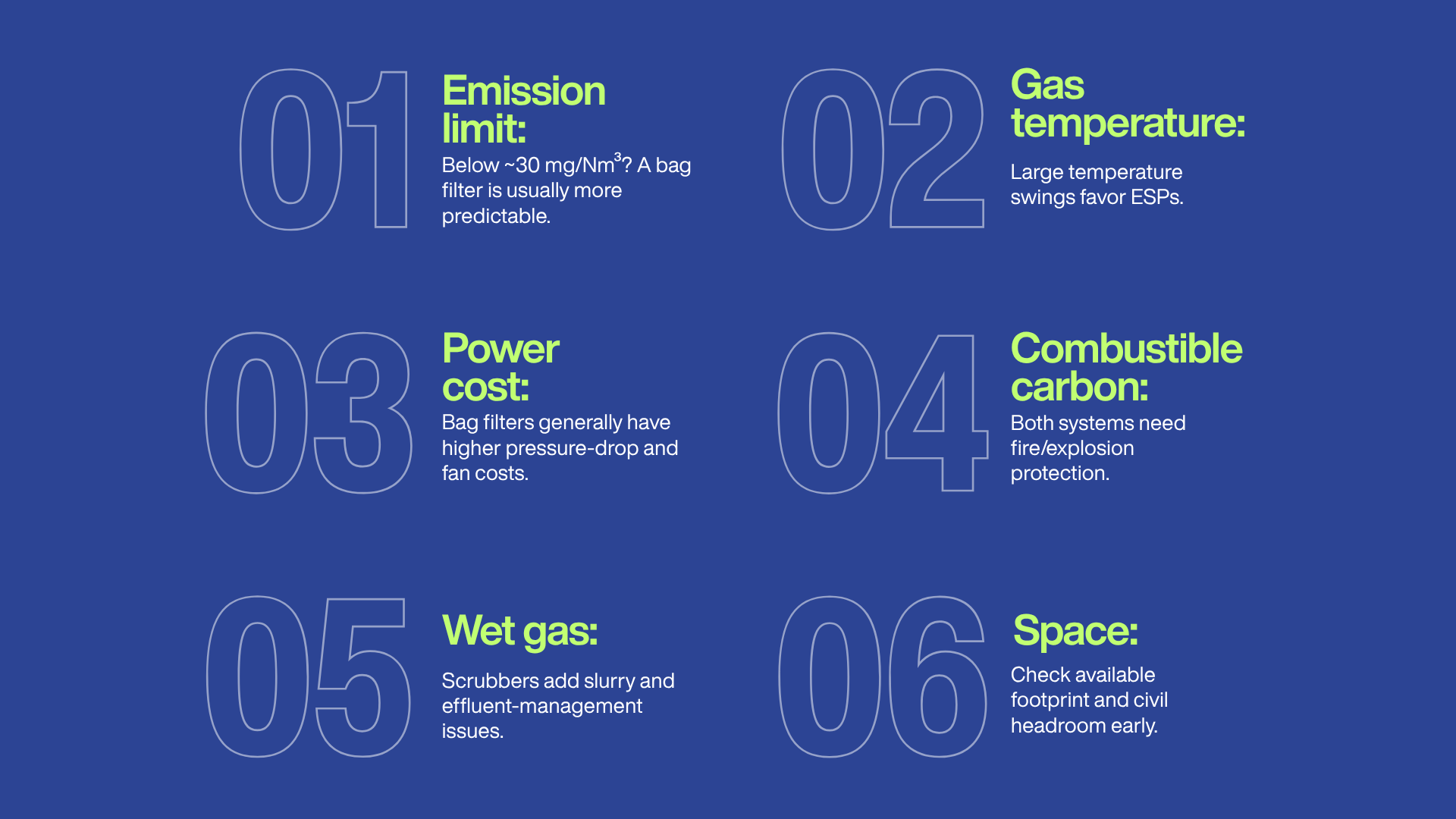
Work through these in order. The first constraint that binds determines the answer.
- What is the strictest limit you may face over the equipment's life? If a 30 mg/Nm³ or lower figure is plausible, a bag filter reaches it more predictably. An ESP can reach very low outlet values, but doing so requires additional fields, and the cost rises steeply as the target falls. TECHFLOW's own engineering comparison notes that achieving below roughly 20 mg/Nm³ with an ESP costs more than a bag filter because of the extra field count.
- How stable is your gas temperature? If the WHRB outlet swings widely, or start-ups routinely push the collector inlet above the media rating, an ESP is the more forgiving choice, or a bag filter must be protected with a properly engineered bypass, dilution damper and emergency quench.
- What is your power tariff and running-hours profile? The pressure-drop gap between an ESP and a bag filter runs through the ID fan every hour of every year. On a continuously operating kiln, that is a real number in the operating cost.
- Is there combustible carbon in the gas? If ABC burnout is unreliable, both technologies need protection: CO interlocks for an ESP, spark detection, and antistatic media for a bag filter.
- Can you handle a wet stream? If not, rule out scrubbers on the main duty. Slurry handling and settling is a second waste problem, and one that also carries effluent obligations under the same notification.
- Do you have space and civil headroom? Retrofits into congested plants frequently come down to this, and it is better established at concept stage than during erection.
For most Indian coal-based DRI kilns, the practical answer has been a multi-field ESP on the main WHRB stack and pulse-jet bag filters across the de-dusting network. Where consent conditions have tightened to 50 mg/Nm³ or below, and the gas temperature can be reliably conditioned, bag filters on the main stack are increasingly viable. TECHFLOW's article on pulse-jet bag filters in sponge iron production covers that case in more detail, and the comprehensive ESP guide sets out the counterpart engineering for precipitators.
The Secondary De-Dusting System
CSE's 2011 study found something instructive. Bag filters were installed at the required locations in the overwhelming majority of plants sampled: 98% at coal crushing, 96% at iron ore crushing, 98% at transfer points, 99% at cooler discharge. And yet high fugitive emissions were recorded during inspection at 68% of plants in the 2008-09 sample. During night inspections, 100%.
Installation was not the problem. Function was.
Fifteen years on, the equipment is better, and enforcement is sharper, but the underlying lesson holds: a de-dusting system fails at the hood and the duct far more often than at the filter.
Pickup point schedule
| Pickup point | Why it emits | Design notes |
|---|---|---|
| Coal crusher inlet/outlet | Impact-generated fines, high release velocity | Full enclosure; two pickups (inlet and discharge); explosible dust precautions |
| Coal and ore screens | Vibration lifts fines continuously | Enclose the screen deck, not just the chute |
| Belt conveyor transfer points | Induced air from falling material | Skirt boards, settling zone, pickup downstream of the impact point |
| Kiln feed/mixing area | Combined fines, continuous release | Hood positioned against prevailing draught |
| Cooler discharge | Warm, moist, dusty; double flap valve leakage | Sized for thermal buoyancy, not just dust |
| Vibrating screens (product) | Fine DRI and char, highly abrasive | Abrasion-resistant duct; generous transport velocity |
| Magnetic separators | Fines shed at the separation point | Multiple small pickups beat one large one |
| Intermediate bins | Displacement air on filling | Bin vent filters sized on fill rate |
| Product house/bagging | Intermittent, high intensity | Local extraction at the fill point; telescopic chutes |
| Char handling | Self-heating, high carbon | Antistatic media, spark detection, no dead legs |
The three engineering numbers that decide whether it works
1. Capture velocity at the source: A hood only works if it generates enough air velocity at the point where the dust is released to overcome that dust's own momentum and any cross-draught. Standard industrial ventilation practice (ACGIH's Industrial Ventilation: A Manual of Recommended Practice) puts dust released at low velocity into moderately still air in the region of 0.5–1.0 m/s, and actively generated dust into a zone of rapid air motion substantially higher. A hood designed on air volume alone, without checking the velocity it produces at the release point, will underperform no matter how good the filter behind it is.
2. Transport velocity in the duct: Iron-bearing and char dust is heavy and abrasive. Conveying velocities for heavy dusts in industrial ventilation practice sit broadly in the 20–25 m/s band. Below that, dust drops out in horizontal runs, the duct progressively chokes, the system starves, and the hoods stop capturing, usually months after commissioning- so the cause is rarely connected to the effect. Above it, you erode elbows quickly. Wear-back elbows and abrasion-resistant liners at every change of direction are not a premium option on this duty.
3. Air-to-cloth ratio at the filter: Generic guidance places pulse-jet cleaning in the region of 6–10:1 in ft/min (roughly 1.8–3.0 m/min) and reverse-air at 2–4:1 (roughly 0.6–1.2 m/min). Treat these as orientation only. Fine, abrasive, warm DRI dust warrants the conservative end of any range, and the actual figure must come from your dust and gas data: particle size distribution, inlet concentration, moisture, temperature profile, and the outlet concentration you are contracted to hold. An aggressive A/C ratio is the cheapest way to make a quotation look competitive and the most reliable way to guarantee short bag life.
The de-dusting system sourcing guide works through how these parameters translate into total cost of ownership across a 10–15 year window.
Filter Media Selection: Getting The Temperature Window Right
For any bag filter on a DRI duty, media selection is a two-sided constraint. There is an upper bound set by the fibre's thermal limit and a lower bound set by the acid dew point. Operating outside either destroys bags.
| Medium | Approx. continuous limit | Strengths | Watch for |
|---|---|---|---|
| Polyester | ~130–150 °C | Low cost, standard dry dust | Only suitable on cool DE points, never main gas |
| PPS (Ryton/Procon type) | ~190 °C (≈375 °F) | Strong acid and alkali resistance, hydrolysis resistant | Lowest heat tolerance of the high-temperature group; oxidation at elevated O₂ |
| P84 (polyimide) | ~230–240 °C | Excellent fine-dust capture, better acid resistance than PPS | Severely hydrolysis-sensitive; unsuitable where moisture is present |
| Fiberglass | ~260 °C continuous, peaks to ~280 °C | High temperature at moderate cost | Brittle; poor tolerance of aggressive pulse cleaning and rough handling |
| PTFE | ~260 °C (≈500 °F) | Broadest chemical resistance, superior cake release, moist heat | Highest cost |
| ePTFE membrane on a base felt | Set by the base fabric | Surface filtration; lowest and most stable outlet emissions | Membrane integrity depends on correct cage and pulse design |
Two rules that prevent most media failures:
- Design to the peak, not the average. A bag rated for your normal 180 °C will not survive a start-up excursion to 240 °C. Specify against the worst credible temperature, including start-up, shutdown, upsets and soot-blowing, and install high-temperature trip protection with a bypass or emergency dilution.
- Stay above the acid dew point. SO₃, HCl and HF vapours condense in the 120–160 °C region, producing micro-droplets of corrosive liquid that attack the fibre and blind the cake. On a coal-fired kiln with variable sulphur in the feed, this is a live risk, particularly on start-up and during low-load operation. Hopper heating, duct insulation and a controlled warm-up procedure are part of the answer.
Where both acid attack and high temperature are present, a PTFE or PTFE-laminated construction is the technically clean answer. It costs more per bag and frequently less per year. TECHFLOW's overview of bag filter types and applications sets out the cleaning-mechanism differences that interact with these media choices.
Common Mistakes That Cost DRI Plants Their Compliance Record
1. Sizing the ESP or bag filter to the national standard. Consent conditions tighten; national minimums are floors. Plants that specified 100 mg/Nm³ equipment now find themselves buying additional fields or a full replacement.
2. Treating the ABC as a burner, not as a control device. Incomplete burnout sends CO and carbon downstream into a high-voltage device. This is a safety issue before it is an emissions issue.
3. No power backup for the APC system. When the ESP drops out, the cap lifts. Continuous power supply to pollution control equipment is a CREP requirement precisely because this is the sector's most common failure mode.
4. No interlocking. Without it, the APC system is optional from the operator's point of view. With it, stopping the APC system stops the feed. CSE's inspection data showed the difference between plants that ran ESPs at night and plants that did not was rarely technical.
5. Hoods designed on air volume rather than capture velocity. Two hoods drawing the same CMH can perform completely differently depending on their geometry and distance from the release point.
6. Under-specified duct velocity on abrasive dust. Choked ducts fail silently and are usually diagnosed only after fugitive emissions have already been recorded.
7. Ignoring the dust discharge system. Rotary airlock valves, screw conveyors, and pneumatic conveying lines on ESP and bag filter hoppers see abrasive, sometimes hot, sometimes carbon-rich dust. When they block, the hopper fills, the collector's effective height reduces, and outlet emissions rise again, with no obvious alarm.
8. No sampling ports or access platform. A physical omission that generates enforcement action on its own, independent of the actual emission value.
9. Buying on lowest capital cost. The right comparison is total cost of ownership across ten to fifteen years: energy through the ID fan, filter bag replacement cycles, compressed air, downtime, and the cost of a single closure direction.
10. Not planning for the collected dust. Ten-plus tonnes a day of carbon-bearing dust with no destination becomes a stockpile, then a fugitive source, then a finding.
The Collected Dust Is A Resource, Not A Liability
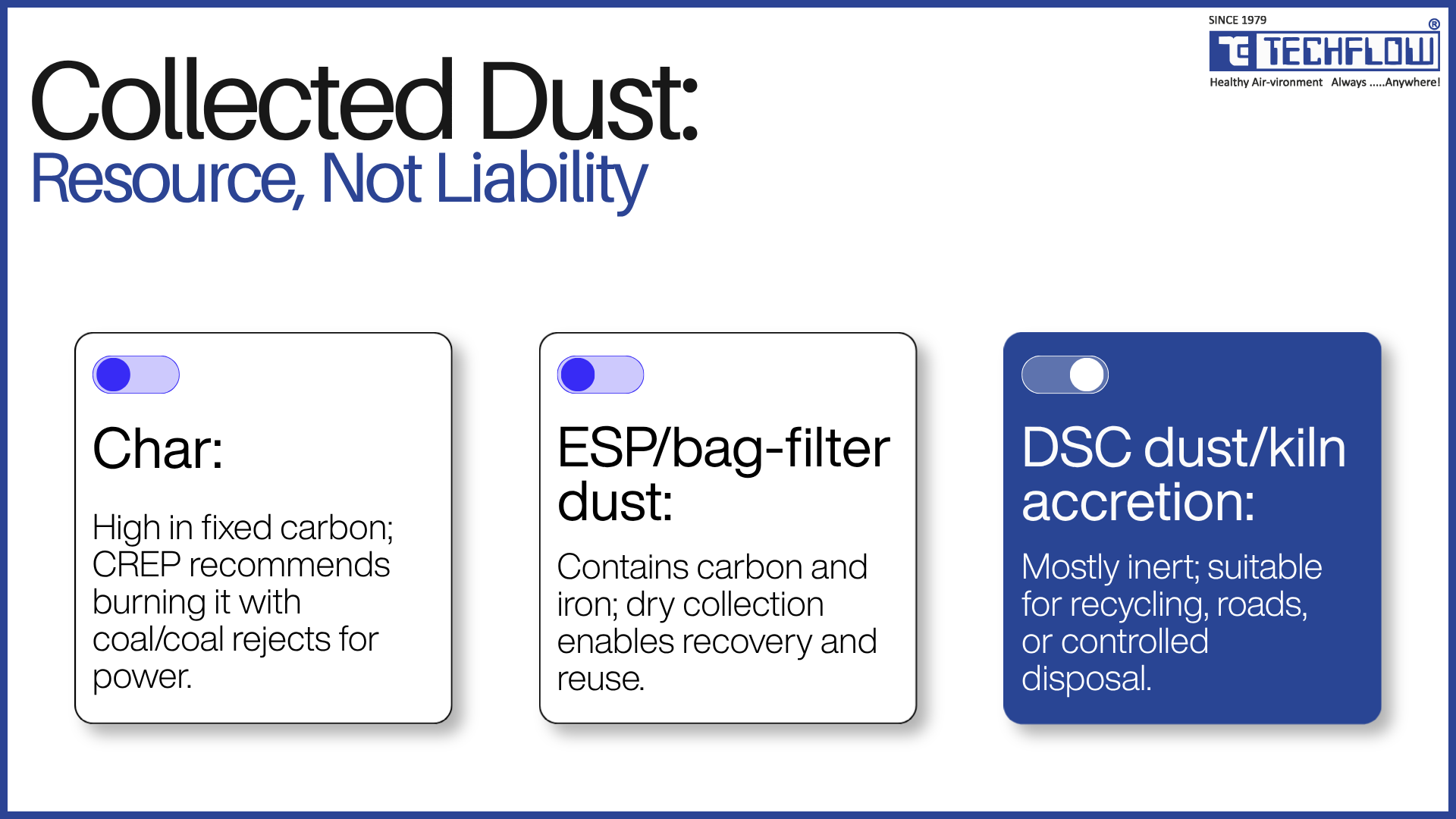
Three streams leave a well-run APC system, and all three have a better destination than a heap.
Char. High in fixed carbon. CREP recommends that plants of 0.066 MTPA and above install a fluidised bed combustion boiler and burn char, mixed with coal or coal rejects, for power. Where a plant is too small for its own boiler, a shared boiler across a cluster is explicitly contemplated. Disposal in agricultural fields is specifically discouraged.
ESP and bag filter dust. The Hospet characterisation cited earlier roughly 14% carbon and 19% iron in a very fine dust indicates why beneficiation and combustible recovery from this stream has attracted genuine research attention. Published work has also examined its use in brick manufacture. The design implication is upstream: specify a dry collector and a dry conveying route if you want a recoverable product.
DSC dust and kiln accretion. Coarser, largely inert. CREP suggests kiln accretions be used in road construction or landfilling, and that flue dust from pollution control equipment be recycled or reused appropriately.
Designing the dust-handling side of an APC system for recovery rather than disposal changes the equipment list: dry collection, sealed rotary airlock valves, screw or pneumatic conveying to a covered silo, and a silo vent filter rather than an open hopper and a tipper truck.
How To Evaluate An Air Pollution Control Partner For A DRI Plant
Use these questions. The answers separate engineering companies from equipment sellers.
- What gas and dust data do you need before quoting? A supplier who quotes from kiln TPD alone has not designed anything. They should ask for gas volume, temperature profile including excursions, inlet dust concentration, particle size distribution, moisture, sulphur in coal, and the outlet concentration required.
- What outlet emission will you guarantee, and under what conditions? Get the guarantee, the reference conditions, and the test protocol in writing.
- What A/C ratio or specific collection area are you designing to, and why? They should be able to justify the number against your data, not against a standard catalogue value.
- How have you handled the temperature window? Ask specifically about start-up, upset, and acid dew point protection.
- What is the dust discharge arrangement? Airlocks, conveying, and where the dust ends up. If they have not thought about this, they have designed half a system.
- What ID fan margin have you allowed over the fouled pressure drop?
- How does the system interlock with the kiln? And what happens on power failure?
- What is the 10-year consumables and energy cost? Ask for it as a number, not a reassurance.
- Can you show DRI-specific installations? Kiln gas is not boiler flue gas and is not cement kiln gas. Sector-specific experience is not interchangeable.
- Who provides after-sales support, and from where? Response time on a tripped ESP is measured in hours of lost production.
Bringing It Together
An air pollution control system in a DRI plant is not a device bolted onto the end of a kiln. It is a temperature-management system, a combustion-completion system, a particulate-collection system, a materials-handling system, and a compliance-evidence system, and it fails at whichever of those is weakest.
Three things are worth carrying away.
- First, specify against the strictest limit you may plausibly face over the equipment's life, not today's floor.
- Second, establish whether your binding constraint is the main stack or the fugitive network before committing capital, because the answer determines where the money should go.
- Third, design the dust discharge route with the same seriousness as the collector, because a collector whose hoppers do not empty is a collector that does not work.
The plants that will be operating comfortably in 2035 are the ones being engineered to that standard now.
How TECHFLOW works with DRI plants

TECHFLOW has been designing and manufacturing air pollution control, dust collection and pneumatic conveying systems since 1979, operating from a 35,000 sq. m. manufacturing facility in Ahmedabad, Gujarat, and serving steel, sponge iron, cement, power, foundry, mining and process industries in India and internationally.
For DRI and sponge iron plants, that covers the primary gas-cleaning train electrostatic precipitators and pulse-jet bag filters, with cyclone pre-cleaners where the duty calls for them.
Through to the complete secondary de-dusting network, centrifugal fans and blowers, ducting and dust conveying. Full details of TECHFLOW's DRI plant capability are on the Air Pollution Control Systems for DRI Plants page.
Frequently Asked Questions (FAQs)
The national minimum standard for coal-based sponge iron plants is 100 mg/Nm³ of particulate matter, notified under G.S.R. 414(E) dated 30 May 2008; gas-based plants are held to 50 mg/Nm³. Carbon monoxide must not exceed 1% by volume. State Pollution Control Boards frequently impose stricter limits through consent conditions; 50 mg/Nm³ is common, and the stricter figure prevails.
Neither is universally better. An ESP has a much lower pressure drop and therefore lower fan power, and tolerates temperature excursions better, but its efficiency depends on dust resistivity, which varies with coal quality. A bag filter reaches low outlet concentrations more predictably and is unaffected by resistivity, but needs careful temperature management and ongoing bag replacement. Where consent limits are tightening below roughly 50 mg/Nm³ and gas temperature can be conditioned reliably, bag filters are increasingly chosen; where limits are moderate and running hours are high, ESPs remain strong.
The dust settling chamber removes coarse dust by dropping gas velocity so heavier particles settle out. The after-burning chamber does something different; it introduces excess air to burn residual carbon monoxide and unburnt carbon in the gas. The DSC is a mechanical separator; the ABC is a combustion device. Both sit upstream of the waste heat recovery boiler.
Because fugitive control depends on a distributed network of hoods and ducts rather than one large device, and it degrades invisibly. Hoods designed on air volume rather than capture velocity, ducts sized below transport velocity for abrasive dust, and blocked dust discharge lines all reduce capture without triggering any alarm. CSE's field study found near-universal installation of bag filters at required locations alongside widespread fugitive emissions during inspection; the equipment was there and not working.
Kiln waste gas leaves at roughly 850–900 °C. After the after-burning chamber, it is hotter still. A waste heat recovery boiler typically brings it down to around 200 °C at its discharge before the final collector, and the cleaned gas leaves the stack at around 80 °C. These are indicative figures; your actual profile depends on kiln size, coal, ABC operation, and boiler design.
Yes. Iron and steel are among the 17 categories of highly polluting industries required to install online continuous emission monitoring systems with real-time transmission to CPCB and the concerned SPCB. CPCB's September 2025 directive further required registration and connection to the OCEMS/ODAMS portal, with PTZ camera integration and geotagged monitoring stations.
30 metres is the notified minimum, but the requirement scales with sulphur dioxide emission rate: 40 m at 33.1 kg/hr, 50 m at 69.6 kg/hr, 60 m at 127.8 kg/hr and 70 m at 213.6 kg/hr. Because SO₂ load follows the sulphur content of the coal, a change of coal source can change the stack height you should have.
Yes, and the collection method determines whether it can be. Char is commonly burnt in a fluidised bed combustion boiler for power. CREP recommends this for plants of 0.066 MTPA and above. ESP dust from coal-based DRI carries meaningful carbon and iron content and has been studied for combustible recovery and for use in brick manufacture. Dry collection with sealed conveying preserves those options; wet scrubbing converts the same material into slurry with a disposal cost.
The most common causes are high dust resistivity, indicated by low secondary voltage, suppressed current, and high spark rates across all fields simultaneously; dust accumulation from failed rapping or a blocked hopper discharge, which reduces the collector's effective height; and gas volume exceeding design following a kiln capacity increase. Field-wise electrical trending against a commissioning baseline will usually distinguish between them.
There is no meaningful single figure, because cost is driven by gas volume, required outlet concentration, temperature profile, dust characteristics, the number of de-dusting pickup points and the dust handling arrangement. The more useful question is total cost of ownership across ten to fifteen years, which includes ID fan energy, filter bag replacement cycles, compressed air, planned downtime and the risk cost of non-compliance. Two systems with similar capital cost can differ substantially on that basis.


