


Key Takeaways
- ESP spares and maintenance work best as one system: daily T-R trending, graded inspections, consequence-based spares stocking, and well-planned outage repairs.
- Transformer-rectifier voltage, current, and spark rate reveal ESP condition better than any other reading. Judge the inlet-to-outlet trend, not one meter.
- Give hopper discharge faults top priority. A hopper can fill in 4 to 24 hours and permanently misalign plates and electrode frames.
- Stock spares by failure consequence, lead time, compatibility, and obsolescence risk. Let unit cost decide quantity, not whether a part is stocked.
- A well-designed ESP tolerates roughly 10% of wires out of service, but losing several wires in one gas lane sharply raises emissions.
- A de-energised ESP can hold up to 15 kV of static charge, so apply visible grounding chains before anyone enters or touches internals.
- Treat every interval and threshold here as a starting point. Confirm it against OEM instructions, your fuel, dust behaviour, and permit conditions.
Quick answer: ESP maintenance combines shift-by-shift monitoring of transformer-rectifier (T-R) readings and opacity, a graded schedule of inspections, a critical-spares stock chosen by failure consequence and lead time, and internal repairs during planned outages. The goal is to catch electrode, rapper, hopper, and T-R faults early, hold collection efficiency steady, and avoid forced shutdowns. Every intervention depends on strict high-voltage isolation, visible grounding, and site-approved safety procedures.
Why ESP Maintenance Matters For Reliability And Compliance
An electrostatic precipitator (ESP) sits on the emission path of a coal- or biomass-fired power plant and is one of its main air pollution control systems. When it drifts out of specification, opacity rises, the unit risks breaching its particulate limit, and operators may have to cut boiler load to stay compliant.
The limits leave little room for error. Under the Ministry of Environment, Forest and Climate Change notification of 7 December 2015, coal-based thermal power units in India must meet particulate matter limits of 100, 50 or 30 mg/Nm³, depending on whether they were installed before 2004, between 2004 and 2016, or from 2017 onwards. Limits can also be revised by later directions, such as a Commission for Air Quality Management direction of February 2026 that revised PM norms, so confirm the limit that currently applies to your unit with your State Pollution Control Board. TECHFLOW keeps a reference list of CPCB emission norms by industry for quick checks.
The difficulty is that an ESP hides its wear inside a sealed, energised casing. Faults build quietly: a few broken wires, a hopper filling faster than it empties, a rapper out of adjustment, an insulator starting to track. Each is cheap to fix early and expensive to ignore.
This checklist is written for operations and maintenance engineers at power plants. It draws on U.S. Environmental Protection Agency (EPA) operation and maintenance guidance for ESPs and on TECHFLOW's work as an Ahmedabad-based electrostatic precipitator manufacturer operating since 1979.
How An Electrostatic Precipitator Works
An ESP charges the dust particles in the flue gas using a high-voltage corona around its discharge electrodes. The charged particles then migrate to grounded collecting plates. Rappers, such as tumbling-hammer or MIGI rapping systems, strike the plates and electrodes at intervals so the dust layer falls into hoppers. The ash-handling system removes it from there. A transformer-rectifier set supplies the high-voltage DC for each field.
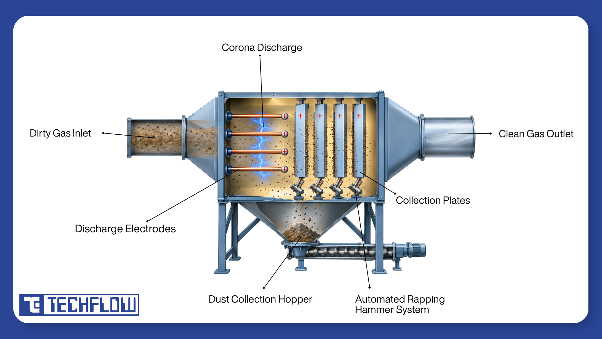
Collection depends on clean, aligned electrodes, working rappers, clear hoppers, and stable power. Maintenance exists to keep each of these within specification. For a fuller explanation of the physics, see TECHFLOW's guide to how electrostatic precipitators work.
Critical ESP Components And How They Fail
Most ESP downtime traces back to a small group of components. These deserve the highest inspection priority.
| Component | Function | Common failure signs | Why it is a priority |
|---|---|---|---|
| Transformer-rectifier (T-R) set and high-voltage controls | Supply and regulate high-voltage DC | Falling secondary voltage or current, abnormal sparking, low insulating liquid level, cracked surge arrester, nuisance trips | A failed set takes a whole field offline |
| Discharge electrodes (wires or rigid frames) | Charge the particles | Broken or slack wires, dust caking, grounds, misalignment | One broken wire can short out an entire field or bus section |
| Collecting plates | Collect the charged dust | Bowing, warping, corrosion, heavy buildup | Close clearances cut operating voltage and promote sparking |
| Rappers (plate and electrode) | Dislodge collected dust | Rappers not striking, weak or excessive force, worn linkages or coils | Rapper failure leads to buildup and steady efficiency loss |
| Support and shaft insulators, bushings | Isolate high-voltage parts | Cracks, carbon tracking, moisture, leakage to ground | A failed insulator grounds the field |
| Hoppers and ash evacuation | Store dust and discharge it to the ash-handling system, often via pneumatic conveying | Level alarms, slow discharge, caking, bridging | Pluggage can permanently misalign plates and frames |
| Control panels and automatic voltage controllers | Regulate power and protect the set | Erratic control, repeated trips, alarm faults | Poor control wastes power and hides real faults |
| Electrical connections, bus ducts and grounding | Carry high voltage and provide safe grounding | Loose terminals, arcing, corrosion, damaged ground paths | Loose connections cause arcing and are a direct safety hazard |
| Auxiliaries (hopper heaters, insulator heaters, seal-air fans) | Prevent condensation and keep dust free-flowing | Heater failure, low seal-air pressure, condensation | Failures lead to corrosion, tracking, and pluggage |
How To Monitor ESP Performance Every Shift
Daily readings are your earliest warning system, so it helps to know what normal looks like before working through any checklist.
- Voltage and current: Record primary and secondary voltage and current for every T-R set each shift. EPA guidance treats these as the single best indicator of ESP performance. Meters flicker with normal sparking, so log the highest value held for at least a fraction of a second.
- Trend across fields: In a healthy ESP, corona power density rises from the inlet to the outlet fields as dust is removed. A fault confined to one field usually points to a mechanical cause in that field. A shift across all fields usually points to dust or process conditions.
- Spark rate: High spark rates with low current in all fields suggest high dust resistivity. High current with little or no sparking in all fields suggests low resistivity.
- Opacity: Watch the transmissometer in real-time mode, because 6-minute averages smooth out rapping spikes. A stable baseline with brief rapping spikes is normal, while a rising baseline means collection is slipping. In high-efficiency ESPs, rapping reentrainment can account for 50 to 70% of outlet emissions, so tuning the rapping pattern often helps more than pushing voltage.
- Gas temperature: A change as small as about 8°C (15°F) can noticeably shift power levels and opacity, mainly through its effect on dust resistivity. A significant drop between inlet and outlet may indicate air inleakage. Confirm it with oxygen readings.
- Air-load and gas-load V-I curves: Take air-load curves on a cool ESP with no gas flow: when new, after the first shutdown, and after every off-line maintenance job. Identical fields should give nearly identical curves. Residual dust on wires and plates shifts a curve to the right, and comparing before-and-after curves shows whether a repair worked. Gas-load curves, taken in service from the outlet field towards the inlet, sit to the left of air-load curves because sparking starts at lower voltage and current when particles are present.
Never rely on one parameter. Electrical trends, opacity, and temperature together give a far clearer picture than any single reading.
ESP Preventive Maintenance Checklist By Interval
The intervals below follow a typical fly ash precipitator schedule published in EPA training material. Treat them as a baseline. EPA itself recommends setting inspection frequency through a formal in-house procedure that follows the vendor's recommendations, so adjust each line for your ESP design, fuel, dust, and operating history.
Every shift (unit running)
- Record voltage, current, and spark rate for every T-R set, and log opacity on a shift data sheet. Note any T-R set that is switched off.
- Confirm hoppers and the ash removal system are discharging normally. Dust discharge faults get the highest repair priority, because dust left in the bottom of the ESP can cause severe plate misalignment.
- Confirm rappers are operating. EPA guidance suggests checking at least daily, ideally during routine T-R readings. A maintenance-check cycle can test every rapper in 2 to 5 minutes.
- Check control-room ventilation and investigate any abnormal arcing in T-R enclosures or bus ducts.
- Review the shift sheets at handover and raise work orders for anything abnormal.
Weekly
- Check and clean control-cabinet air filters.
- Inspect control-set interiors for dust, overheating, and loose terminals.
- Compare the week's field-by-field T-R trends against your baseline.
Monthly
- Check the standby top-housing pressurising fan and its thermostat.
- Check hopper heater operation.
- Test hopper level alarms.
Quarterly
- Clean and check rapper and vibrator switch contacts.
- Check transmissometer calibration.
Every six months
- Clean and lubricate access-door dog bolts, hinges, interlock covers, and test connections. Use powdered graphite only on interlock parts, never oil or grease.
- Check the T-R insulating liquid level and the surge-arrester spark gap.
- Inspect the casing for deterioration, leaks, abnormal vibration, or noise.
Annually (internal inspection)
- Inspect the internals and clean the top housing or insulator compartment and all insulating surfaces.
- Check and correct electrode alignment.
- Clean contactors, check the tightness of all electrical connections, and check and adjust switchgear.
- Clean and inspect gasketed connections and tighten rapper insulator connections.
- Record areas of corrosion.
During every outage
- Record air-load and gas-load readings during and after the outage.
- Clear all shorts and hopper buildups, and check all alarms, interlocks, and safety devices.
- For outages over 72 hours: clean and check control-set interiors, inspect grounding devices, and record the amount and location of residual dust on electrodes.
- For outages over 5 days: clean all internal bushings.
How To Prioritise Critical ESP Spares
Not every spare earns shelf space, and not every shelf spare is genuinely critical. Rank each part against these five criteria.
- Failure consequence: Ask what a failure does to emissions and load. A single broken wire can short out a field or bus section, which in a smaller ESP may be a third to half of the collecting area. Inlet fields collect the most dust, so parts serving them usually rank higher. Some ESPs can meet limits with part of the unit de-energised, while others have no margin at all.
- Procurement lead time: A part that takes weeks or months to source belongs on the shelf even if it rarely fails. A part available locally within a day often does not.
- Compatibility: Match each spare to the ESP's make, model, field, and vintage. Electrode profiles, rapper types, and T-R ratings vary, and generic substitutes may not fit or perform.
- Operating conditions: Corrosive or high-resistivity dust, operation near the acid dew point, and frequent start-stops raise failure rates for wires, electrodes, and insulators. Stock these items deeper.
- Obsolescence: Controllers and electronic cards on older ESPs go out of production. Identify end-of-life items early and secure spares or a documented upgrade path before support ends.
A workable rule: decide whether to stock a part by consequence, lead time, and obsolescence risk. Let unit cost guide the quantity, not the decision.
ESP Spare Parts Stocking Template
Use this as a starting template. Set minimum and maximum levels for each line, tie reorder points to real lead times, and adjust to your plant's risk profile and OEM recommendations.
| Spare part | Function | Failure signs | Inspection | Stocking guidance |
|---|---|---|---|---|
| Discharge electrodes, wires and weights | Charge the dust | Breaks at top or bottom, slack wires, erosion, crimps | Each outage; update the wire failure chart | High priority on weighted-wire designs and with corrosive or high-resistivity dust |
| Collecting plate sections and spacer bars | Collect the dust | Bowing, warping, corrosion, heavy buildup | Alignment and visual check each outage | Long lead time; stock for known problem fields |
| Rapper assemblies, coils, hammers and drive parts | Shed the dust layer | Rappers not striking, worn linkages or bearings | Shift operation check; full inspection each outage | Keep common rapper types and wear parts on hand |
| T-R set (or critical sub-assemblies) and controller cards | Supply and regulate high-voltage DC | Low output, trips, liquid level or surge-arrester faults | Shift readings; six-monthly liquid and spark-gap check | Critical: high consequence, long lead time, obsolescence risk |
| Support and shaft insulators, bushings | Isolate high-voltage parts | Cracks, carbon tracking, moisture, leakage | Clean and inspect at the annual inspection and long outages | Keep a set for each insulator type |
| Hopper heaters, insulator heaters, seal-air fan parts | Prevent condensation and caking | Heater failure, low seal-air pressure | Monthly checks | Moderate priority; failures lead to pluggage and tracking |
| Rotary airlock valves, feeders and conveying wear parts | Discharge collected ash | Jamming, leaks, motor faults | Shift discharge check | Keep rotors, seals and wear parts in stock |
| Grounding chains and hooks, access-door gaskets and seals | Safety and sealing | Wear, damage, air inleakage | Each outage | Low cost, high safety value; always keep spares |
How To Plan An ESP Shutdown And Outage
Most real ESP maintenance happens during outages, because the internals are only reachable when the unit is cold and isolated. Plan each outage like a project.
Before the outage
- Review T-R trends, opacity history, and the wire failure chart to list suspect fields.
- Stage the spares those jobs need, along with scaffolding, lighting, and tools.
- Prepare isolation, permit-to-work and confined-space entry paperwork, and brief the crew.
Shutting down
A typical boiler ESP shutdown sequence from EPA training material runs as follows. Follow your OEM procedure where it differs.
- As boiler load falls, de-energise fields one at a time, starting with the inlet field, to keep opacity in check.
- De-energise the outlet field once fuel flow stops and combustion air falls below about 30% of rated flow.
- Keep rappers, ash removal, seal-air and hopper heaters running so collected dust clears from plates and wires.
- About 4 hours after boiler shutdown, stop seal-air and hopper heaters and secure ash removal. About 8 hours after, stop the rappers.
- Empty every hopper completely. Confirm the dust level from the upper access inside the ESP, not from the level alarm, before any hopper door is opened.
In an emergency, de-energise all T-R sets first, then follow steps 3 and 4.
Inside the ESP
- Inspect plates and electrodes and correct misalignment. Many ESPs tolerate up to about 3/16 inch (roughly 5 mm) of misalignment, but always work to the OEM's tolerance.
- Replace broken wires and log their locations. Never cross a replacement wire with another one; replace overlong, slack wires instead.
- Clean insulators and bushings, and look for cracks and carbon tracks.
- Clear hopper buildups and shorts, and check guide frames for wear.
- Tighten and inspect electrical connections and grounding devices.
- Record the amount and location of residual dust on electrodes, and any corrosion, for trend tracking.
ESP Restart And Commissioning Checklist
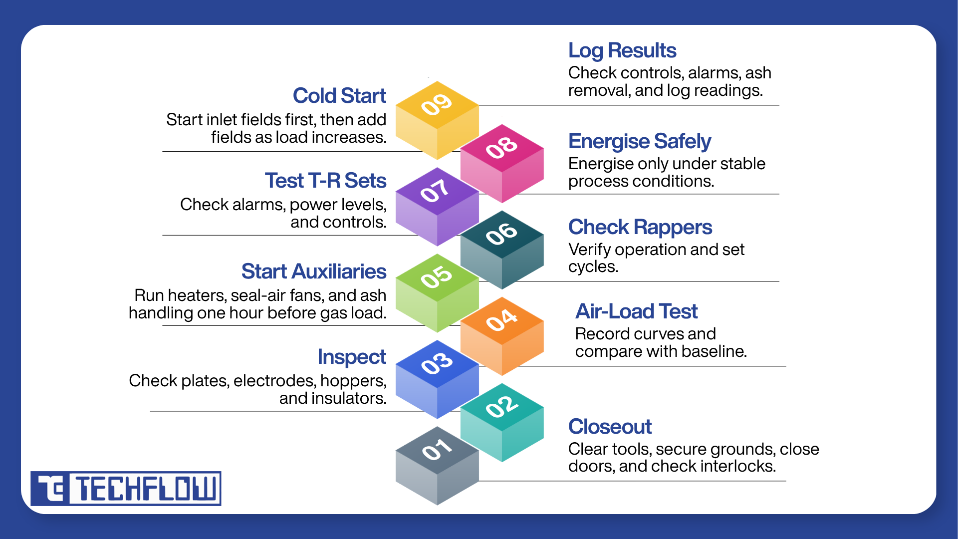
Re-energising carelessly can undo good maintenance or damage the unit. Run a structured sequence, starting pre-operational checks at least 2 hours before gas load.
- Close out the work. Complete all maintenance items, remove tools and debris, account for every person, return grounding chains to their storage brackets, close access doors, and confirm interlocks work with all keys accounted for.
- Run the pre-start inspection. Plates should be free of bows and heavy dust. Discharge electrodes should show no breaks or slack wires and move freely in their guides. Hoppers should be clear with level detectors unobstructed, and insulators should be clean and dry with no carbon tracks.
- Record air-load curves. Take them while the ESP is still cool with no gas flow, and compare them with the pre-outage baseline to confirm the faults are cleared.
- Start auxiliaries at least an hour before gas load. Switch on hopper and insulator (bushing) heaters, start the seal-air fan, and put the ash-handling system in operating mode.
- Check the rappers. Run a rapid sequence, confirm every rapper operates, then set cycle time and intensity.
- Test the T-R sets. Test-energise each set, check local and remote alarms, set power levels, then de-energise until gas conditions are right.
- Energise only when the process is stable. On coal-fired boilers, wait until coal firing is confirmed so combustible gases cannot collect in the ESP. The EPA-cited procedure energises after flue gas at about 93°C (200°F) has passed through for 2 hours.
- Handle cold starts carefully. Energise from the inlet field with voltage just below sparking, and bring in further fields as load builds.
- Confirm and log. Within 2 hours of energising, confirm normal T-R control, alarm functions and ash removal, then log the commissioning readings.
Common ESP Problems And How To Troubleshoot Them
EPA's 1985 operation and maintenance manual groups major ESP performance problems into seven areas: dust resistivity, dust buildup, wire breakage, hopper pluggage, component misalignment, changes in particle size distribution, and air inleakage. The table splits resistivity into its high and low forms. Treat the indicators as prompts to investigate, not confirmed diagnoses.
| Problem | Possible causes | Typical indicators | Verification steps |
|---|---|---|---|
| High dust resistivity | Fuel change (such as low-sulphur coal), low flue-gas moisture or SO₃, gas temperature shifts | Low voltage, suppressed current and high spark rates in all fields; tenacious dust; opacity puffs at rapping | Compare current and spark-rate trends inlet to outlet; review fuel and gas temperature; consider conditioning only after engineering review |
| Low dust resistivity | Excess unburnt carbon, alkali-rich biomass ash, over-conditioning or high SO₃ | Low voltage, high current, little or no sparking in all fields; opacity puffs after plate rapping | Check combustion and unburnt carbon, fuel and conditioning; tune the rapping pattern |
| Dust buildup on electrodes | Failed or inadequate rapping, sticky dust, operation below the acid or moisture dew point | Rising opacity; V-I curve shifted right (more voltage needed for the same current) | Run the rapper check cycle; compare gas temperature with dew point; check for water carryover such as a tube leak |
| Wire breakage | Electrical erosion from repeated sparking at close clearances, wear at guide frames, corrosion, crimps, crossed wires | A field or bus section shorting out; repeated trips on one section | Log locations on the wire failure chart; check alignment and guide frames at the next outage; check for dew-point operation |
| Hopper pluggage | Fallen wires or weights, undersized discharge equipment, using hoppers for storage, poor insulation or heating, inleakage at hopper doors | Heavy or bursty sparking over the hopper, falling voltage, T-R trips; often invisible on meters until the hopper is nearly full | Check level indicators, heaters and discharge equipment; clear the hopper; inspect alignment afterwards |
| Component misalignment | Warped plates, skewed electrode guide frames, insulator failure, hopper buildup | Sparking at lower voltage and current in one field | Measure clearances during the outage against OEM tolerance; correct before restart |
| Change in particle size | Process or combustion change producing more fine particles (0.2 to 0.9 µm is the hardest range to collect) | Rising opacity without a single-field fault; suppressed current in inlet fields spreading further downstream | Review recent process and fuel changes; compare inlet field trends; arrange particle size testing |
| Air inleakage | Leaking access or hopper doors, flanges, ductwork, open sample ports | Temperature drop and oxygen rise across the ESP, local sparking, audible in-rush at doors, local corrosion | Measure temperature and oxygen across the ESP; inspect walls from inside in daylight for light penetration; reseal |
One principle runs through every row: the electrical readings tell you a field is in trouble, but rarely why. Many different faults produce the same meter signature, and one failure can trigger others. Combine electrical trends, opacity, temperature, records, and internal inspection before committing to a repair.
What ESP Maintenance Records To Keep
Good records turn maintenance from firefighting into trend management, and consent or permit conditions often require documented inspection and maintenance history.
- Shift data sheets. T-R readings, opacity, hopper status, and any T-R set out of service, reviewed at the end of each shift for maintenance needs.
- Work orders. One for every repair or adjustment, logging parts, labour, findings, field, and component.
- Wire failure chart. The only reliable way to see where wires have broken or been removed, and whether losses are bunching in one gas lane. Log rapper frequency and intensity changes, insulator and heater repairs, alignment work and T-R repairs the same way.
- Baseline curves. Air-load and gas-load V-I curves, kept permanently as the reference for drift and for checking repairs.
- Design records. Specific collection area, number of fields and T-R sets, sectionalisation, T-R ratings and design gas conditions, so operating data can be compared with what the ESP was built for.
- Spares data. Stock levels, reorder points, lead times and consumption per part. Over time, this shows which parts wear fastest at your plant.
- Retention. Keep records for the period your consent to operate or permit requires, and keep them accessible for audits and the next troubleshooting job.
Safety Rules For ESP Maintenance
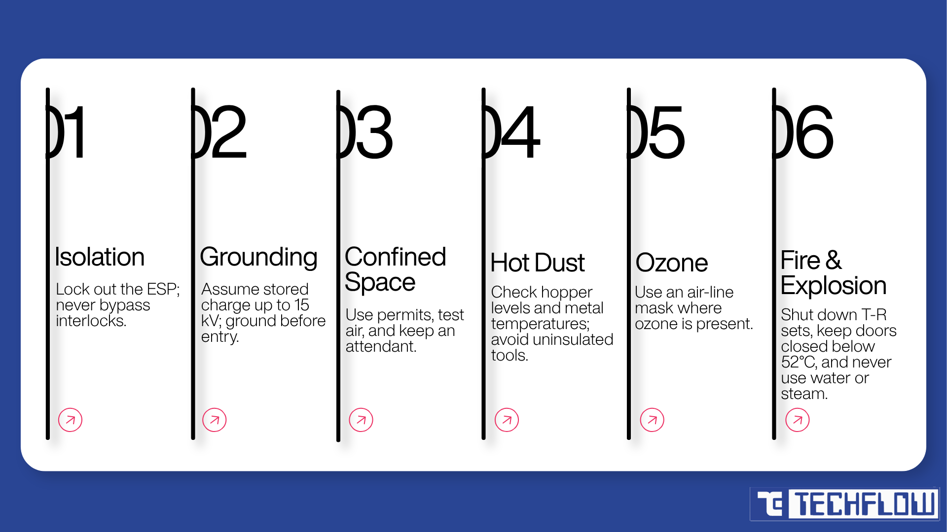
An ESP is a high-voltage machine with stored electrical energy, hot surfaces, confined internal spaces and large volumes of fine dust. No task is routine enough to skip the safety procedure. The points below are general good practice. Always follow your site's approved procedures, and allow only trained, authorised people to work on an energised or recently energised ESP.
- Isolation and interlocks: Isolate and lock out the ESP and its auxiliaries before work. Never bypass or tamper with the key interlock system, and destroy any extra interlock keys.
- Stored charge and grounding: A de-energised ESP can hold a static charge of up to 15 kV. Attach grounding chains before entering the precipitator, T-R switch enclosure or bus ducts. The only ground you can trust is one you can see.
- Confined-space entry: Internal access is confined-space work. Use a written permit, test the atmosphere before entry, and keep a trained attendant outside.
- Hot dust and hot metal: Never open a hopper door unless the dust level is confirmed below the door, because hot dust can flow like water and cause fatal burns. Test metal temperature with the back of the hand, and never poke hoppers with an uninsulated metal bar.
- Ozone: Energised discharge electrodes produce ozone. Wear an air-line mask when entering the precipitator, flues or stack where ozone may be present, not a filter, cartridge or canister respirator.
- Fire and explosion: If a boiler malfunction could carry volatile gases or heavy carbon into the ESP, shut down all T-R sets immediately. Where high carbon levels are known, keep access doors shut until the ESP cools below 52°C (125°F). If a hopper fire is suspected, empty that hopper, or shut down the T-R sets above it until it can be emptied. Never use water or steam, which can release hydrogen.
In India, confined-space entry into chambers, pits, flues and similar spaces where dangerous gas or dust may be present is governed by Section 36 of the Factories Act, 1948 and your state factory rules. General safety requirements for operating and maintaining electrical apparatus are set by the CEA (Measures relating to Safety and Electric Supply) Regulations, 2023. In the United States, the equivalent references are OSHA's 29 CFR 1910.147 (lockout/tagout) and 29 CFR 1910.146 (permit-required confined spaces).
Get ESP Spares And Maintenance Support From Techflow
ESP reliability comes mostly from doing ordinary things on time: reading the meters, checking rappers and hoppers, stocking the right spares, using outages well, and keeping honest records. When a part does need replacing, matching it correctly to the ESP matters more than finding the cheapest option.
TECHFLOW designs and manufactures PrecipaX electrostatic precipitators for boilers, power plants, steel, cement, sugar and other industries, and supports them with tuning and replacement parts. For application-specific reading, see TECHFLOW's guides to ESPs for boilers and thermic-fluid heaters and ESP systems for boiler dust.
Planning an outage or building a critical-spares list? Talk to TECHFLOW's engineering team
Frequently Asked Questions (FAQs)
Monitor T-R readings and opacity every shift, then follow a graded schedule of weekly, monthly, quarterly, six-monthly and annual checks, with internal inspection during outages. Set the final frequencies through a formal in-house procedure based on the OEM's recommendations, operating history, fuel and dust behaviour.
Prioritise parts whose failure takes a field offline and that take longest to source: T-R sets or their critical sub-assemblies, controller cards, discharge electrodes, insulators, rapper parts and ash-discharge wear parts. Match every spare to the ESP's make, model, and field, and check older electronics for obsolescence.
Yes, within limits. EPA guidance indicates performance generally holds with up to about 10% of wires removed, provided no more than 5 to 10 wires are missing from any one gas lane. Track every failure on a wire replacement chart so losses do not bunch up in one lane.
Usually a change in T-R voltage, current, or spark rate, often alongside a rising opacity baseline. Because several faults produce similar electrical signatures, compare the trend across fields and confirm the cause before replacing parts.
A hopper can fill in 4 to 24 hours, and the electrical readings may not show it until the hopper is nearly full. Dust building up into the collecting zone can push plates and electrode frames out of alignment or warp plates permanently, so performance stays down even after the hopper is cleared.
It starts as a fuel, process, or gas-condition issue, but it raises the maintenance load through heavy sparking, wire breakage from electrical erosion, and dust that is hard to rap off. Short excursions can be managed operationally; resistivity far outside the design range may need gas conditioning or engineering changes.
Isolate and lock out the ESP and its auxiliaries, keep the key interlock system intact, and attach grounding chains before entry, because a de-energised ESP can hold up to 15 kV. Treat entry as permit-controlled confined-space work, use an air-line mask where ozone may be present, and confirm hoppers are empty and metal is cool.
EPA's 1985 operation and maintenance manual groups the major problems into seven areas: dust resistivity, dust buildup, wire breakage, hopper pluggage, component misalignment, changes in particle size distribution, and air inleakage. Many of these produce similar electrical readings, and one fault often triggers another, so confirm the root cause before starting a repair.
Confirm all work is complete, tools and debris are removed, everyone is out, grounding chains are back in their brackets, and every interlock key is accounted for. Then record air-load curves on the cool ESP, start the hopper heaters, insulator heaters, and seal-air fan, prove every rapper works, and test the T-R sets and alarms before energising under stable gas conditions.


