


Key Takeaways
- A rotary airlock valve meters dry bulk solids into or out of a pneumatic conveying line while sealing the pressure difference between two zones.
- Flow path comes first: drop-through for general duty, blow-through for pressurised lines and sticky powders, side-entry for fragile or oversized particles.
- The rotor, not the housing, drives performance. Closed, open, helical and adjustable-tip rotors each suit a different material behaviour.
- Size by calculation: mass flow, bulk density, a realistic fill efficiency and rotor speed decide the pocket volume you need.
- Match duty class to the job. Standard-duty suits low-pressure gravity feed; heavy-duty handles abrasive, continuous or high-pressure conveying.
- On combustible dust, a rotary valve can act as a passive explosion isolation device under NFPA 69, NFPA 68, NFPA 660 or EN 15089.
- Air leakage and rotor wear are the common field failures, and correct tip clearance, rotor choice and scheduled maintenance prevent both.
A rotary airlock valve meters dry powders, granules or pellets into or out of a pneumatic conveying line while holding back the pressure difference that drives the system. It is a small part with outsized influence. Specify it well, and the line runs for years on routine maintenance. Specify it poorly, and the rest of the plant works against that one valve, shift after shift. A sound choice comes down to five linked decisions: flow path, rotor, duty class, material of construction and sizing.
What A Rotary Airlock Valve Does, And Why Pneumatic Conveying Needs One
The airlock principle
A rotary airlock valve works like a revolving door for bulk solids. Material passes from one pressure zone to the next in small, sealed batches, and the air on either side never mixes freely. Rotary feeder, rotary lock and airlock all name the same device.
Pneumatic conveying depends on that pressure difference. A blower either pushes air through the pipeline under positive pressure or pulls it under vacuum, and the material rides the airstream across the plant. Connect a hopper at atmospheric pressure straight to a pressurised pipe and three things go wrong at once: air escapes, efficiency drops, and dust blows back out of the feed point. The valve closes that gap. Its pockets fill on one side, rotate past a tight clearance, and discharge on the other, while the housing keeps the two pressures apart.
Where the valve sits in the system
In most layouts, the valve sits in one of two places:
- At the feed point, below a silo, bin or hopper, metering material into the line at a set rate.
- At the discharge point, below a cyclone, dust collector or filter receiver, dropping collected material out of the system without breaking the vacuum or pressure inside.
Both jobs are the same at heart. Move and meter material while holding the pressure differential that keeps the system efficient.
How A Rotary Airlock Valve Works
A rotary airlock valve turns a multi-vane rotor inside a close-tolerance housing, carrying material from the inlet to the outlet in sealed pockets.
The main parts of the valve
Five parts do all the work:
- Housing: a cast or fabricated body, usually cylindrical, that holds the rotor and defines the inlet and outlet openings.
- Rotor and shaft: a multi-vane wheel, typically six to twelve blades, on a central shaft.
- End plates: the covers that close the rotor chamber and often carry the shaft seals.
- Shaft seals and bearings: packing or mechanical seals that stop material and air escaping along the shaft. On heavier-duty valves, the bearings sit outboard, away from the product, for longer life.
- Drive: a gear motor, usually through a reducer, that turns the rotor at a set speed. Direct-drive and chain-drive arrangements are both common.
How the rotor cycle works
Material drops through the top opening into a rotor pocket, the gap between two vanes. As the rotor turns, that pocket carries its load toward the outlet, sealed against the housing wall by a small, exact clearance. At the bottom, the pocket lines up with the outlet, and the material falls or is blown into the conveying line. An empty pocket then swings back to the inlet, and the cycle repeats.
The clearance between rotor tip and housing separates a good valve from a poor one. Too tight and the rotor rubs, wears and seizes. Too loose and air blows straight through the pockets, wasting blower capacity and upsetting the line. Most industrial valves hold this gap to a fraction of a millimetre, set wider or tighter for the material and the temperature.
Rotor speed is the second control. Too slow and the feed pulses. Too fast and the pockets cannot fill in time. Worse, pressurised air from the discharge side pushes back into the inlet, fluidises the incoming powder, and stops it settling into the pockets at all.
Flow-Path Types: Drop-Through, Blow-Through And Side-Entry
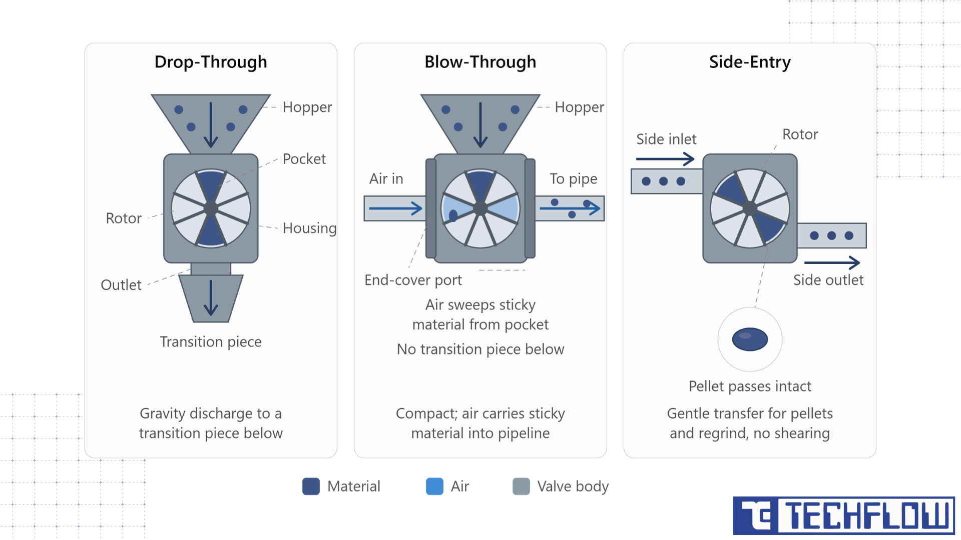
Three flow-path designs cover almost every application. Each solves a different mechanical problem.
Drop-through valves are the default. Material enters at the top and, once the pocket comes around, drops by gravity out of the bottom into a hopper, transition piece or the line below. They come in the widest range of sizes.
Blow-through valves skip the gravity drop. Side ports in the end covers connect straight to the conveying line, so the airstream runs through the rotor pockets and carries material into the pipe. The valve stays compact, needs no transition piece beneath it, and clears sticky materials well, because the conveying air sweeps each pocket. It is used almost only in pneumatic conveying, on both pressure and vacuum lines.
Side-entry valves move the inlet and outlet to the side of the rotor. That reduces shearing and jamming, which suits plastic pellets, regrind and other particles large or fragile enough to break on a top-to-bottom path.
A quick rule of thumb: drop-through for general duty, blow-through for compact installs and sticky materials on a pressurised line, side-entry when particle size or fragility rules out the other two. For food-grade and hygroscopic materials, a quick-clean variant adds tool-free rotor access for sanitation. TECHFLOW builds its Roto Tuff rotary airlock valve range in all four, which is why flow path is usually the first question an engineering team settles before sizing.
Rotor Types And Pocket Designs
Rotor geometry, not the housing, decides how a material behaves inside the valve. The flow path sets how material enters and leaves. The rotor sets how it travels in between. The right rotor is often the difference between a valve that runs for years and one that jams in a shift.
- Closed rotors have solid ends on both sides of each pocket. That tightens the seal and limits leakage, which suits non-abrasive materials where cross-leakage matters more than easy discharge.
- Open rotors leave one side of the pocket open. Material enters and clears more easily, at the cost of slightly more leakage, so they fit cases where some leakage is acceptable and flow is the priority.
- Helical, or staggered, rotors offset the pockets along the rotor. Discharge comes out smoother and more continuous, with fewer pulses, which helps processes that need an even, metered feed.
- Reduced-volume rotors shrink the pocket to lower the displaced volume per revolution. They suit cases that need a larger body to avoid bridging over the inlet while keeping the discharge rate low.
- Scalloped or shallow-pocket rotors use curved, shallower geometry to stop sticky material packing into corners, a common problem with straight vanes on cohesive powders.
- Adjustable-tip rotors carry replaceable rubber or urethane strips on the vane edge instead of a fixed metal tip, so the operator can reset clearance as wear occurs rather than replace the whole rotor.
Match the rotor to the actual material, not a catalogue default. The same conveying rate through the wrong rotor can give anything from a leaking, dusty install to a jam on day one.
Standard-Duty Vs Heavy-Duty Rotary Airlock Valves
Not every job needs the same build, and over-specifying wastes money as surely as under-specifying fails early. Most ranges split into two duty classes.
| Feature | Standard duty | Heavy duty |
|---|---|---|
| Typical use | Low-pressure, gravity-fed duty under a dust collector or small hopper | Conveying lines with higher pressure differentials, abrasive or continuous service |
| Bearing location | Often inboard, near the product zone | Outboard, away from the product for longer bearing life |
| Housing | Lighter castings or fabricated bodies | Heavier castings with thicker walls |
| Rotor build | Standard vane thickness | Thick vanes and oversized shafts that resist deflection |
| Materials handled | Dry, free-flowing, non-abrasive dust and powder | Abrasive, heavier or continuously fed bulk solids |
The decision rests on two questions. How much pressure differential will the valve see, and how abrasive or continuous is the duty? A standard-duty valve under a small dust collector runs for years with little wear. The same valve as the primary feeder on a continuous abrasive line burns through bearings and seals far faster than a heavy-duty unit built for the load. The Roto Tuff series is built heavy-duty, with outboard bearings and a rating to 300 degrees C, so a plant moving abrasive fly ash and a plant moving light plastic pellets are matched to the right build rather than handed the same valve.
Materials Of Construction And Coatings
Material choice affects three things at once: corrosion resistance, wear life and hygienic suitability. Decide it on its own merits, not as an afterthought once the rotor and duty class are set.
Cast iron is the standard body material for general industrial duty, with good strength and cost efficiency on non-corrosive, moderately abrasive materials. Mild steel fabricated housings suit cases that need a lighter, weldable structure. Stainless steel, in 304 or 316, is needed wherever corrosion resistance or hygiene matters, including food, pharmaceutical and many chemical duties. The Roto Tuff range is offered in mild steel, cast iron and stainless steel for this reason.
Beyond the base metal, wear protection often sets service life on abrasive materials:
- Hard chrome or ceramic lining on the inner housing resists the scouring of abrasive powders such as sand, minerals or fly ash. On a heavily abrasive line, pairing it with wear-resistant bends protects the pipework the valve feeds.
- Abrasion-resistant rotor tips slow the wear that widens the rotor-to-housing clearance over time and increases leakage.
- Flexible rubber or urethane tips trade some wear resistance for cushioning on brittle materials, reducing particle breakage through the valve.
- For high-temperature service, valves use expanded clearances or special alloys so the rotor can grow thermally without seizing against the housing as it heats.
Dilute-Phase Vs Dense-Phase Conveying
Pneumatic conveying splits into two regimes, and the valve works differently in each.
In dilute-phase conveying, material travels suspended in a fast airstream at low solids concentration. The valve usually acts as the primary feeder, metering material at a steady rate the airstream can carry without settling. The pressure differential across the valve stays modest, so standard drop-through or blow-through valves handle most dilute-phase lines.
In dense-phase conveying, material moves slower and denser, often in slugs rather than a suspended cloud, at higher line pressure. The valve now sees a steeper pressure differential across the rotor, which raises leakage and the load on seals and bearings. Heavy-duty construction, tighter clearances, and sometimes a dedicated pressure-vessel transporter take over from a single rotary valve. Identifying the regime before specifying the valve avoids a common, costly mistake: a standard-duty airlock dropped onto a dense-phase line built for dilute-phase conditions.
How To Size A Rotary Airlock Valve
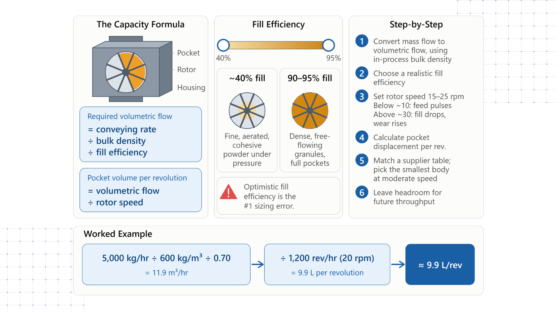
The capacity formula
Every sound sizing method reduces to the same relationship. The volume the valve must displace depends on the conveying rate, the material bulk density and a realistic fill efficiency. The pocket volume per revolution then depends on rotor speed.
Required volumetric flow = conveying rate/bulk density / fill efficiency
Pocket volume per revolution = volumetric flow/rotor speed
Fill efficiency is the figure people get wrong most often. Catalogue tables often assume 100 percent pocket filling, which rarely happens in service. In practice, it runs from about 40 percent for difficult, aerated or fine cohesive powders under pressure, up to roughly 90 to 95 percent for dense, free-flowing granules in good conditions. An optimistic figure here is the single most common reason a correctly calculated valve underperforms once installed. The same displacement logic underpins published rotary valve sizing methods across the industry.
Sizing walkthrough, step by step
- Convert the required mass flow to volumetric flow. Divide throughput in kg/hr or lb/hr by the material's actual in-process bulk density, not its theoretical or compacted density.
- Choose a realistic fill efficiency based on how the material behaves. Coarse, free-flowing solids sit high. Fine, cohesive or aerated powders sit low.
- Set a target rotor speed, generally 15 to 25 rpm for most industrial duty. Below about 10 rpm, the feed pulses. Above about 30 rpm, fill efficiency drops and wear climbs.
- Work out the pocket displacement per revolution from the relationship above.
- Match that against a supplier sizing table and take the smallest body that delivers the volume at a moderate speed, rather than running a smaller valve at its limit.
- Leave headroom for future throughput, so a modest rise in targets does not force a full replacement.
Worked example. A plant needs to move 5,000 kg/hr of a powder at a bulk density of 600 kg/m³, and its aeration suggests 70 percent fill efficiency. Volumetric flow is 5,000 / 600 / 0.70, about 11.9 m³/hr. At 20 rpm, that is 1,200 revolutions an hour, so the pocket displacement needed is about 9.9 litres per revolution. The engineer then matches that against published pocket volumes to pick the size. Because fill efficiency is so easy to overestimate, this is best worked through with the customer's own material data rather than a catalogue default.
Explosion Isolation And Combustible Dust Standards
A rotary airlock valve can act as a passive explosion isolation device. Its rotor pockets and tight housing clearance block flame and pressure from propagating between connected equipment.
This matters because combustible dust is an explosion hazard in many plants. Sugar, flour, wood, plastics and metal powders can all deflagrate where a dust cloud and an ignition source meet. The rotor pockets and the close clearance physically block a flame front and pressure wave from travelling from a collector or receiver back into a silo or upstream process, with no electronics or active control involved.
In the United States, this function is judged against NFPA 69, the standard on explosion prevention systems, alongside NFPA 68 on deflagration venting. Since December 2024, the fundamentals once held in NFPA 652 and 654 sit in the consolidated NFPA 660, Standard for Combustible Dusts and Particulate Solids. In Europe, the reference is EN 15089 on explosion isolation systems, read with the ATEX directive for equipment in potentially explosive atmospheres.
The wording matters. A valve that is "built to" or "compliant with" these standards is not the same as one independently tested and certified against them. Components only required to be compliant are often tested to around 14.5 psig, while third-party certified valves are tested to the material's maximum deflagration pressure, which can be much higher. Where explosion isolation is a real safety requirement, ask for test documentation, not a compliance statement. One limit is worth knowing. An isolation valve blocks a propagating deflagration. It does not stop a steady fire or burning powder, which is why a full dust hazard analysis and layered protection still apply.
Industries That Rely On Rotary Airlock Valves
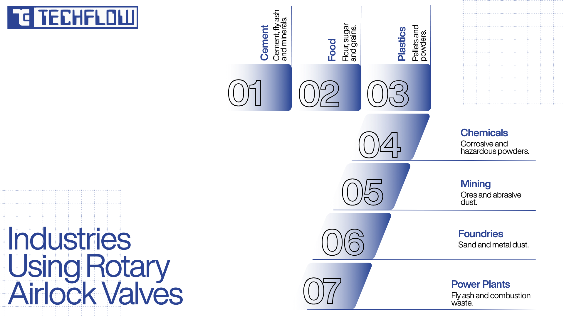
Dry bulk solids move through almost every process industry, so the valve turns up across a wide range of sectors:
- Cement and building materials, moving cement, fly ash and mineral powders from silos into conveying and packing lines.
- Food processing, handling flour, sugar and grains, often with stainless steel and a quick-clean rotor.
- Plastics and polymers, conveying pellets, regrind and powders, where side-entry or gentle rotors reduce particle damage.
- Chemicals and pharmaceuticals, moving powders that may need corrosion resistance, containment or explosion isolation.
- Mining and mineral processing, handling ore and abrasive mineral dust that calls for heavy-duty, wear-resistant builds.
- Foundries and metal processing, where sand reclamation and furnace or shot-blast dust collection rely on airlocks under cyclones and bag filters.
- Power generation, conveying fly ash and other combustion by-products from boilers and pollution control equipment.
In nearly all of them, a rotary airlock also sits under a baghouse or cyclone, dropping collected dust out of the system without breaking its vacuum.
Common Rotary Airlock Valve Problems And Fixes
Every valve wears. Catching the early signs saves material and downtime.
- Air leakage past the rotor: Usually worn rotor tips or a worn housing bore opening the sealing clearance. The fix is tip replacement, re-machining or a rotor swap, not tightening the drive.
- Material bridging above the inlet: The valve is undersized against the inlet, or a cohesive material arches over the pocket. A larger body, vibration assistance or a reduced-volume rotor in a bigger housing usually clears it.
- Rotor jamming or stalling: Often oversized particles, tramp material or sticky buildup in the pockets. Screen the upstream material and pick a shallow or scalloped pocket rotor.
- Early bearing or seal failure: Common when a standard-duty valve sits on a heavy-duty job, or packing seals miss their greasing schedule. Match duty class to the real pressure and abrasiveness.
- Uneven or pulsing discharge: Usually the rotor running too slow or too fast, or a plain rotor where the process needs a smoother helical one.
- Excessive noise or vibration: Usually worn bearings, an unbalanced rotor or drive misalignment. Investigate before it becomes a mechanical failure.
Installation And Maintenance Best Practices
Good mechanical design is half the job. Installation and upkeep decide whether the valve reaches its rated life.
- Mount the valve level and well supported, so the inlet and outlet connections carry no stress that could distort the housing.
- Set the specified rotor clearance at commissioning, then re-check it after the first few weeks as parts bed in.
- Grease bearings and packing seals on a fixed schedule rather than reactively. Seal failure is one of the more preventable causes of downtime.
- Inspect rotor tips for wear, especially on abrasive duty, and adjust or replace before clearance grows enough to leak.
- Keep upstream screening in place so oversized particles, debris or tramp metal cannot enter and damage the rotor.
- Log rotor speed, motor load and any unusual noise, so a developing fault shows up early.
- Train operators to spot the symptoms above, since the person watching the line daily usually notices a change first.
Rotary Airlock Valve Vs Other Isolation Devices
A rotary airlock is not the only way to feed or isolate bulk solids. Each alternative fits a narrower job.
- Double flap valves use two weighted or actuated flaps in sequence to isolate pressure zones with no rotating part. They suit lower-cycle, gravity-discharge duty but cannot match a rotary valve's continuous metered flow on a high-throughput line.
- Diverter valves route material between downstream paths rather than metering it into a pressurised line. They direct flow; they do not seal pressure zones.
- Knife gate valves give an on-off shutoff in a duct or chute but do not meter flow or hold an air seal during continuous running.
- Dome valves give a tight shutoff seal, often at the inlet of a dense-phase transporter, and usually work alongside a rotary airlock rather than replace it.
At most feed and discharge points, the rotary airlock stays the default, because no other single device combines continuous metering, a reasonably tight pressure seal and, where needed, passive explosion isolation.
Rotary Airlock Valve Selection Checklist
Answer these before placing an order:
- What is the throughput in mass flow per hour, and the material's actual in-process bulk density?
- How abrasive, cohesive or fragile is the material, and does that point to a particular rotor or wear protection?
- What pressure differential will the valve see, and does that push toward standard or heavy-duty?
- Is the line dilute-phase or dense-phase, and does the pressure demand extra sealing margin?
- Does the application involve combustible dust and a certified explosion isolation design?
- What temperature range applies, and does it need expanded clearances or special alloys?
- Is hygiene or corrosion resistance a factor, pointing toward stainless steel and a quick-clean rotor?
- What are the space and orientation constraints, and do they favour drop-through, blow-through or side-entry?
- What is the realistic fill efficiency for this material, rather than the catalogue best case?
- What maintenance access and spare-parts support will be available once the valve is running?
Work through the list, and a vague requirement becomes a specification a supplier can quote against accurately the first time.
Roto Tuff Rotary Airlock Valves By Techflow
Everything in this guide, from rotor choice to duty class to sizing discipline, is the daily engineering behind the Roto Tuff range of rotary airlock valves, built by Techflow Enterprises Pvt. Ltd. in Ahmedabad, India. The range handles bulk material in any shape, powder, granule, chip or pellet.
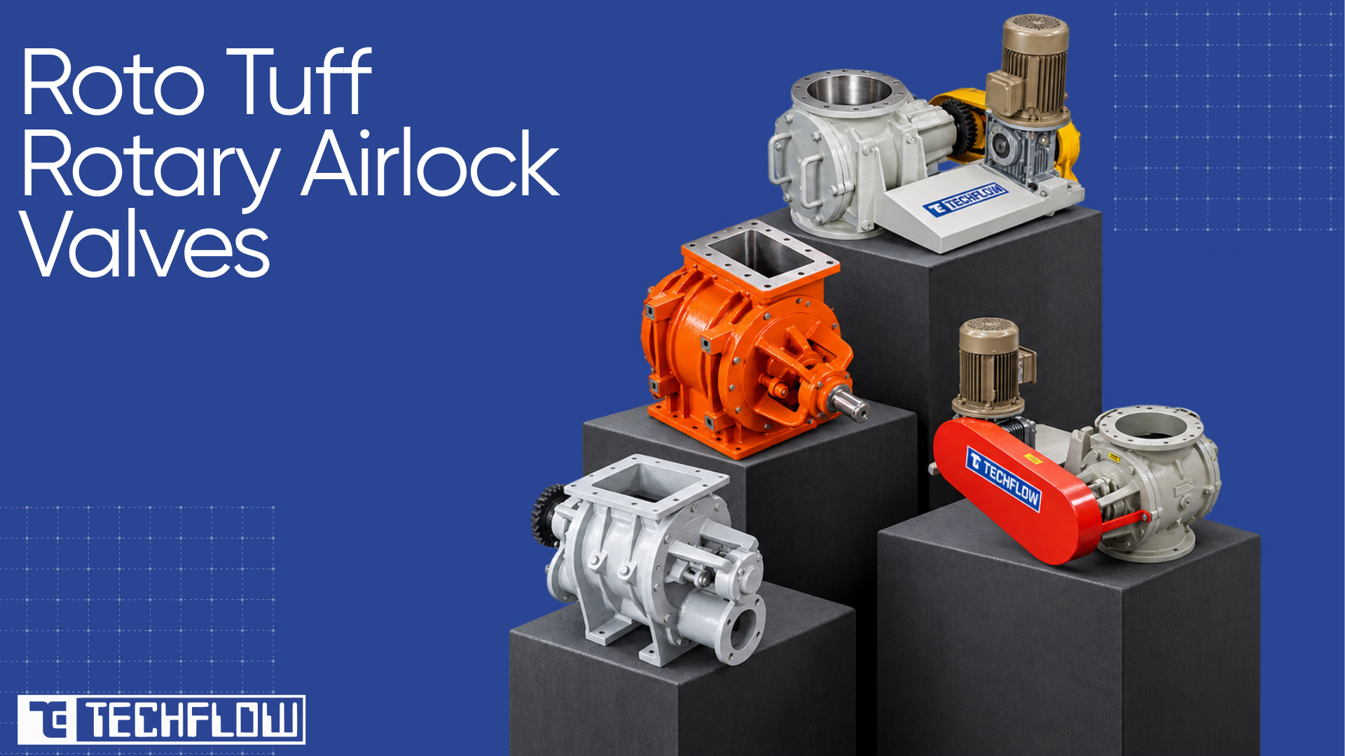
Roto Tuff comes in sizes from 150 to 450 mm, in drop-through, blow-through, side-entry and quick-clean forms, with closed, open, helical and adjustable-tip rotor options and bodies in mild steel, cast iron or stainless steel. It is a heavy-duty valve with outboard bearings, a rating to 300 degrees C and a choice of direct or chain drive. Because it is specified as part of a complete line rather than sold alone, it works alongside the other components TECHFLOW builds: dilute and dense phase transporters, cyclone and bag filter dust collectors, centrifugal blowers, and diverter, knife gate and dome valves.
For the wider picture, TECHFLOW's guide to pneumatic conveying in powder coating, shot blasting and mineral plants shows how the airlock, blower and dust collection equipment work together on demanding lines.
Choosing A Valve That Lasts
A rotary airlock valve is mechanically simple, which is exactly why it gets under-specified. The five decisions in this guide work together: flow path, rotor, duty class, material and sizing. The wrong rotor undermines a correctly sized valve. Loose clearance leaks air and reduces capacity. A skipped explosion-isolation check on a combustible-dust line costs far more than lost throughput.
Handled properly, the result is a valve that runs for years on predictable maintenance instead of surprise failures. The method is the same whether the duty is a small dust collector discharge or the primary feed on a high-pressure dense-phase line. Match the material to the design, then confirm the numbers.
Get The Right Valve For Your Line
Share your material, throughput, and line conditions, and TECHFLOW will match the right configuration, rotor, and material of construction for the job, in sizes from 150 to 450 mm and in drop-through, blow-through, side-entry, or quick-clean form. Explore the Roto Tuff range or request a sizing consultation.
Frequently Asked Questions (FAQs)
It meters dry bulk solids such as powders, granules or pellets from a hopper, bin or dust collector into or out of a pneumatic conveying line, while sealing the pressure difference between the two zones so the system's air pressure or vacuum is not lost.
A drop-through valve discharges by gravity out of the bottom of the housing into a hopper or pipe below. A blow-through valve has ports on the sides of its end covers that connect to the conveying line, so the airstream runs through the rotor pockets and pushes material into the pipe. Blow-through suits compact installs and sticky materials.
Divide the required conveying rate by the material bulk density, then by a realistic fill efficiency, to get the volume the valve must displace per hour. Divide that by rotor speed to get the pocket volume per revolution, then match it against a manufacturer pocket-volume table to pick the size.
Most industrial rotary airlock valves run best between about 15 and 25 rpm. Below about 10 rpm, the feed pulses and becomes unstable. Above about 30 rpm, pocket fill efficiency drops and wear on the rotor and seals climbs.
Standard-duty valves suit low-pressure, gravity-fed duty with non-abrasive materials, using lighter castings and often inboard bearings. Heavy-duty valves use thicker castings, oversized shafts and outboard bearings for higher pressure differentials, abrasive materials and continuous conveying.
Yes, when designed and independently tested for it. It can act as a passive explosion isolation device, using its rotor pockets and tight clearance to block flame and pressure-wave propagation between equipment. Certification against NFPA 69 or EN 15089 confirms this through third-party testing, which is stronger than a general compliance claim.
Air leaks through the clearance between the rotor tips and the housing. The leak grows as that clearance widens with wear, as the pressure differential across the valve rises, or as rotor speed increases past the point where pockets can fill and seal before discharge.
Common materials are cast iron and mild steel for general industrial duty, and 304 or 316 stainless steel where corrosion resistance or hygiene is needed, such as food or pharmaceutical processing. Abrasive-duty valves often add hard chrome or ceramic lining on the housing and wear-resistant rotor tips.
Most industrial valves run through a gear reducer, which brings shaft speed into the practical 15 to 25 rpm range. Direct-drive and chain-drive arrangements are both available, with the geared option standard wherever the valve handles continuous, higher-torque duty.
The terms are used interchangeably. Both describe a multi-vane rotor turning inside a close-tolerance housing. "Airlock" stresses the pressure-sealing function, and "feeder" stresses the metering function, but the hardware is the same.


