


Key Takeaways
- A cyclone separator removes particulate from an airstream using inertial separation alone, with no filter media, no bags, and no moving parts.
- Cut diameter (d50), the particle size a cyclone captures at 50 per cent efficiency, is set primarily by body diameter. A smaller diameter gives a finer cut.
- Standard design inlet velocities are fixed by geometry under the Texas A&M Cyclone Design (TCD) method: roughly 16 m/s for 1D3D cyclones, 15 m/s for 2D2D, and 12 m/s for 1D2D designs, each within about ±2 m/s.
- Standard cyclones capture coarse dust reliably, broadly above 20 microns (μm). High-efficiency, small-diameter designs push the cut point down toward 4 to 7 μm. Below roughly 5 μm, capture falls away for any cyclone.
- Industrial cyclone pressure drop usually falls in the 500 to 2,000 Pascal (Pa) range, a figure that directly drives fan energy cost.
- A multi-cyclone (multiclone) splits total airflow across many small-diameter tubes in parallel, reaching a finer cut than one large cyclone at the same airflow, and typically removes on the order of 80 to 85 per cent of the total dust mass on boilers, cement plants, and kilns as a primary stage.
- Neither configuration reliably captures sub-5 μm dust on its own. Both are standard practice as a primary stage upstream of a bag filter or electrostatic precipitator, not as a final compliance stage.
- TECHFLOW manufactures a full cyclone dust collector range alongside a dedicated MultiClone line, with tube geometry engineered per application rather than sold as one universal part.
Why Cyclone Selection Is an Engineering Calculation, Not a Catalogue Pick
A correctly sized cyclone is quiet, discharges dust steadily and dry, and leaves a clean stack. An undersized one fails recognisably: rising noise, an erratic hopper discharge, and a faint haze at the outlet that was not there at commissioning. That gap rarely comes down to build quality. It comes down to whether inlet velocity, body diameter, and pressure drop were calculated against the plant's real dust, or whether a unit was pulled off a shelf because it was rated for a similar airflow.
Cyclones have no filter media and no moving parts, which is exactly what makes them easy to under-engineer. There is no obvious component to inspect until dust is already escaping the stack. This guide works through the numbers that decide the outcome: inlet velocity targets, how cut diameter behaves, and the real pressure-drop ranges that separate a cyclone built to run for a decade from one that quietly underperforms from day one. It is the same calculation TECHFLOW runs on every cyclone and multiclone system it builds from its Ahmedabad facility, starting from the dust rather than a generic specification sheet.
What Is a Cyclone Separator?

A cyclone separator is a static device that separates suspended solid particles from a gas stream using inertia. Dust-laden air is forced into a spinning vortex inside a cylindrical-conical body. Heavier particles cannot follow the tight curve of the airflow, so they are carried to the wall, lose momentum on contact, and fall to a collection hopper, while cleaned air leaves through the top.
Because separation relies on geometry and airflow rather than a physical barrier, a cyclone has nothing to blind over, saturate, or wear out the way a filter does. That is why it remains the default first stage across much of industrial dust collection, and why TECHFLOW supplies cyclone dust collectors in single, twin, and quad configurations sized to the dust load of each application.
The physics: inertia and centripetal force, not "centrifugal force"
It is common to say that centrifugal force throws dust to the wall. That is a useful shorthand but technically backwards. In the stationary frame of the equipment, a particle's own inertia resists the curved path the airflow forces on it, and that resistance drives it outward into the wall. The force that keeps a particle on a circular path is centripetal force:
F = m × v² / r
Here m is the particle mass, v is the air velocity, and r is the radial distance from the centre. Every design lever in this guide, from body diameter to velocity to cone length, exists to change one of these three terms. Two consequences matter most: heavier and faster particles separate easily, and a tighter radius sharply increases the separating force.
Separation itself works through a two-vortex structure. Dust-laden air enters tangentially near the top and spirals down the cylinder wall as the outer vortex, where particles are thrown outward, loses energy against the wall and slides down the cone toward the dust outlet. As the cone narrows, the rotating airstream accelerates, reverses near the apex, and rises back up the centre as the inner vortex, leaving through the vortex finder as cleaned air. This runs continuously, with nothing to saturate and nothing to wear.
What Is a Multi-Cyclone (Multiclone)?
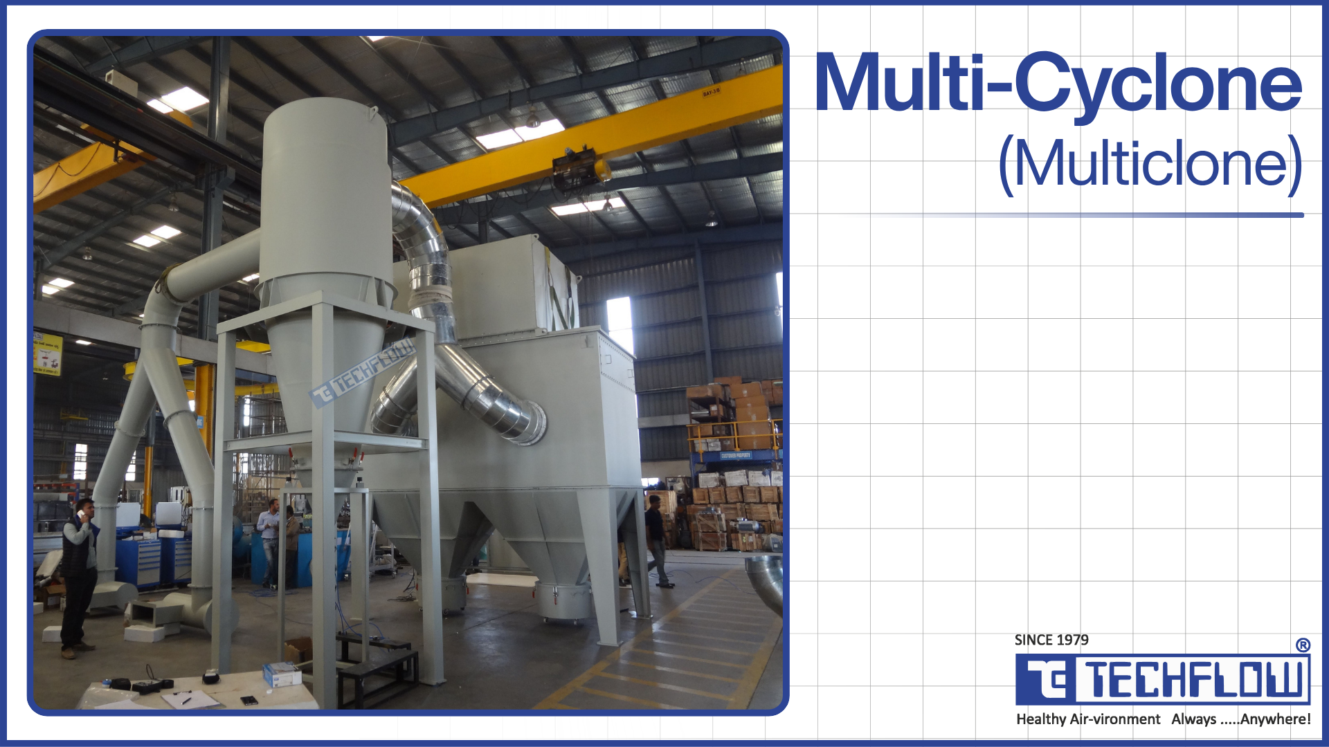
A multi-cyclone, or multiclone, is the second-generation mechanical dust collector that follows the single cyclone. Instead of one large body, it splits the total airflow across many small-diameter cyclonic tubes arranged in parallel inside a shared housing. Each tube runs as its own self-contained cyclone: a spinner vane starts the spiral, dust drops into a common hopper, and cleaned air exits through that tube's individual vortex finder.
A multiclone does not use a new separation principle. It applies the same inertial separation as a single cyclone, but at a smaller tube diameter, which is exactly what buys a finer cut. In practice, it serves as a primary separator that reduces the dust load reaching a downstream bag filter, and in combustible-dust processes it doubles as a primary spark trap. TECHFLOW builds its MultiClone range with different cyclonic tube types for different applications, because the heart of any multiclone is the tube, and the right tube for gritty foundry dust is not the right tube for lightweight biomass ash.
Cut Diameter (d50): The Number That Decides Capture
The cut diameter, written d50, is the particle size a cyclone captures at exactly 50 per cent efficiency. It is not a flat efficiency rating. It is the anchor point of a grade-efficiency curve, the relationship between particle diameter and the probability of capture. A cyclone with a d50 of 10 μm captures most particles well above 10 μm, roughly half the particles at 10 μm, and progressively fewer below it.
Cut diameter responds to a defined set of variables:
- Smaller body diameter gives a lower d50 and a finer cut, at the cost of lower capacity per unit.
- Higher inlet velocity gives a lower d50, at the cost of higher pressure drop and faster wall wear.
- A longer cylinder and cone give a lower d50, at the cost of a taller, more expensive unit.
- A larger vortex finder outlet raises d50 to a coarser cut, in exchange for lower pressure drop.
Diameter is the dominant lever, and the reason is arithmetic. Because radius sits in the denominator of the force relationship, halving the cyclone diameter roughly doubles the separating acceleration at the same velocity. That single fact is the entire justification for the multiclone: you reach a finer cut by making each separating body smaller, not by making one body work harder.
Standard Inlet Velocity Targets, and Why They Are Fixed
Cyclone inlet velocity is not a free variable an engineer tunes by feel. The Texas A&M Cyclone Design (TCD) method, widely used across industrial and agricultural dust control, specifies fixed design velocities by geometry. Peer-reviewed cyclone design work puts these at roughly 16 m/s for tall, high-efficiency 1D3D cyclones, 15 m/s for balanced 2D2D designs, and 12 m/s for high-throughput 1D2D designs, each with about ±2 m/s tolerance.
The nomenclature explains the numbers. In a label such as 1D3D, the "D" is the barrel diameter, and the digits give the relative lengths of the barrel and the cone. A 1D3D cyclone has a barrel one diameter unit and a cone three diameter units in length, which makes it tall and efficient. A 2D2D cyclone has a barrel and cone each two diameter units, balancing efficiency against throughput. A 1D2D cyclone is shorter and built for high volume at lower pressure drop. The barrel diameter is chosen so that the design airflow passing through the inlet cross-section produces the target velocity for that geometry.
Drift outside this band, in either direction, and the consequences are specific:
- Run below the target, and the separating force falls short of what the design cut diameter needs. Dust that should be captured escapes, with no alarm to flag it and no visible mechanical sign that anything is wrong.
- Run above the target, and separation gains flatten out quickly while erosion at the inlet, barrel, and cone rises sharply. That is a real problem in abrasive-dust settings such as foundries and mineral processing, where chasing a marginally finer cut by pushing velocity can shorten equipment life far more than it improves capture.
Cyclone Pressure Drop and the Fan Energy Bill
Pressure loss across a typical industrial cyclone falls in the 500 to 2,000 Pa range, roughly 50 to 200 millimetres water column (mmWC). That band is wide enough that where a unit lands inside it has compounding cost consequences, because pressure drop is the single largest driver of fan energy.
A worked estimate for a mid-size single cyclone commonly lands near 950 to 1,000 Pa, about 100 mmWC, before ducting, dust loading, and system losses are added. That figure should be checked against the actual fan curve, not assumed from a datasheet. On a fan running continuously across multiple shifts, a design sitting even 500 Pa above what the duty requires adds a measurable, ongoing electricity cost across the year. This is precisely why inlet velocity should not be pushed past its design target to chase a marginal efficiency gain. The trade rarely pays for itself.
High-efficiency designs and multiclones sit at the top of that range or beyond it, because the smaller diameters and higher velocities that buy a finer cut also add resistance. That extra pressure drop is a legitimate operating cost and should be modelled at the design stage, not discovered on the first utility bill.
Real Cyclone Efficiency: Where the Spec Sheet and the Plant Floor Disagree
A cyclone does not have a single efficiency number, for two separate reasons.
The first is design. A standard body and a high-efficiency, small-diameter body sit on completely different grade-efficiency curves. A standard cyclone is a coarse-dust device. A high-efficiency design shifts the whole curve toward finer particles, at the cost of higher pressure drop. The table below gives realistic capture behaviour for both classes.
| Particle size band | Standard cyclone | High-efficiency small-diameter design |
|---|---|---|
| Above 20 to 25 μm | High, commonly above 90 per cent | Very high |
| 10 to 20 μm | Moderate to high | High |
| 5 to 10 μm | Falls off noticeably | Moderate, with a d50 around 4 to 7 μm |
| Below 5 μm | Weak | Weak |
The second reason is the dust itself. Overall mass efficiency depends on the particle size distribution feeding the cyclone, not only on the design. The same cyclone with a d50 of 10 μm can post 95 per cent mass efficiency on a coarse, sandy dust and far less on a fine ash, because the share of mass sitting below the cut point is completely different. A quoted efficiency figure therefore means little on its own. It needs both the design class and the dust's size distribution to be meaningful.
There is also a gap between ideal and field numbers, driven by manufacturing tolerances, gasket wear, and air in-leakage that no datasheet accounts for. Real installations commonly run below their theoretical curve for these reasons.
Below roughly 5 μm, the limit is physical rather than a matter of build quality. A particle that light is so weakly separated that aerodynamic drag competes on even terms with the force pushing it to the wall. Its mass has simply dropped too far for inertia to win, so it follows the air out through the vortex finder. That ceiling is the exact reason cyclones are paired with downstream fine-particulate equipment rather than asked to finish the job alone. The practical rule for specification is blunt: size a cyclone for the coarse fraction it can genuinely capture, and plan separately for anything meaningful below 5 μm.
How a Multiclone Applies the Same Physics in Parallel

Because each tube in a multiclone has a far smaller diameter than a single cyclone handling the same total flow, each tube generates much more separating force. Several small cyclones running in parallel therefore reach a finer cut than one oversized cyclone at the same total dust load. The array is built from a defined set of parts, and each one matters:
- Cyclonic tubes ("clones"), typically 100 to 250 mm in diameter, are the parallel separating units doing the actual work.
- The inlet plenum distributes air across all the tubes. It is the part most often underestimated, because a poorly designed plenum overloads some tubes and starves others, quietly undermining even well-built tube geometry.
- Spinners are the vanes that impart the initial spiral at each tube's inlet.
- Vortex finders provide one clean-air outlet per tube.
- The dust hopper and casing form the shared collection chamber and structural housing that keep the array airtight.
This gain does not come free. A multiclone runs a higher pressure drop than a single cyclone at equal airflow, because smaller tubes and the higher velocities needed to hit a finer d50 both add resistance. A multiclone array frequently sits at or beyond the top of the 500 to 2,000 Pa band that single cyclones occupy, and that is a real, continuous fan-energy cost.
Configuration scales with airflow and dust load. Single or twin cyclones handle lower-volume, coarser dust in simple installations. Quad configurations step up for heavier loading. Hexa, octa, and larger modular multiclones handle high-volume exhaust on boilers, kilns, and large process lines. TECHFLOW carries this range under its dedicated MultiClone line, with tube geometry matched to the dust, because treating a foundry tube and a biomass-ash tube as interchangeable is a common and avoidable mistake.
Single Cyclone vs Multi-Cyclone: Direct Comparison
Both devices separate dust by inertia. The difference is how the airflow is divided, and that one choice cascades into cut diameter, pressure drop, footprint, and cost. The table sets the two configurations side by side on the parameters that decide a purchase.
| Parameter | Single Cyclone | Multi-Cyclone |
|---|---|---|
| Body diameter | One large diameter, sized to total airflow | Many small diameters, typically 100 to 250 mm, sized individually |
| Cut diameter (d50) | Coarser, limited by the diameter needed to pass full airflow in one body | Finer, because each small tube generates more separating force |
| Pressure drop | Lower, usually the lower end of 500 to 2,000 Pa | Higher, greater than an equivalent single cyclone at the same airflow |
| Fan energy cost | Lower, ongoing | Higher, ongoing, a direct result of higher pressure drop |
| Footprint | Larger, for equivalent airflow at a fine cut | Smaller, a compact tube array versus one oversized body |
| Capital cost | Lower, simpler to fabricate and install | Higher, more components and plenum engineering |
| Maintenance points | Fewer: one body, one hopper, one vortex finder | More: every tube, spinner, and vortex finder is a potential wear point |
| Sensitivity to plenum design | Not applicable, single inlet | High, uneven airflow across tubes directly degrades performance |
| Typical airflow fit | Lower to moderate volume | High volume, especially where a fine cut is also required |
| Typical application | Woodworking, general coarse-dust extraction | Biomass boilers, cement plants, lime kilns |
| Available from TECHFLOW as | Single or twin cyclone | Quad, hexa, or octa MultiClone |
Where Each One Wins
A multi-cyclone earns its place where high airflow meets a fine cut-diameter requirement, exactly the case where a single body would have to be either impractically large or impossibly narrow to hit both targets at once. Multiclones are the established first stage on biomass boilers, cement plants, and lime kilns, typically removing on the order of 80 to 85 per cent of the total dust mass before exhaust reaches anything downstream. They are also the natural choice in space-constrained retrofits, where a compact tube array fits where an oversized single body will not. As a protective pre-stage, a multiclone reduces the dust load reaching a downstream bag filter, and in combustible-dust processes it doubles as a primary spark trap.
A single cyclone wins the opposite scenario: coarser, lower-volume dust where one body already reaches target efficiency without paying for multiclone complexity and its added pressure drop. Where lowest capital cost is the priority, a single cyclone is simpler, cheaper, and faster to install. And on tight energy budgets, particularly continuous, high-runtime processes, the lower pressure drop of a single body compounds into real savings across years of operation.
A Worked Sizing Example: Biomass Boiler Exhaust
Take a biomass boiler exhaust stream running roughly 20,000 Cubic Feet per Minute (CFM), carrying fly ash in the 8 to 15 μm range, in a plant with limited floor space around the boiler house.
A single cyclone sized to pass 20,000 CFM at the standard 15 to 16 m/s inlet velocity would need a body diameter large enough that its resulting d50 sits above the 8 to 15 μm target. That means a meaningful fraction of the ash passes through uncaptured. Shrinking the diameter to reach that finer cut solves the cut-point problem but creates a new one: a single body can no longer pass 20,000 CFM without exceeding a safe inlet velocity.
Splitting the same volume across roughly twelve to twenty small-diameter tubes resolves both constraints at once. Each tube reaches the target d50 at a design-appropriate velocity, and the array collectively handles the full airflow. The accepted cost is a higher pressure drop than a single large cyclone would have carried, offset by finer capture and a footprint that fits the existing boiler house. This is the specific engineering logic behind most multiclone installations on combustion exhaust: a direct response to a fine cut-diameter target that a single body cannot physically reach without becoming impractically undersized for the airflow.
Cyclone vs Bag Filter vs ESP vs Wet Scrubber: The Sequencing Question
For most plants, the more consequential decision is not which cyclone configuration to buy. It is whether a cyclone alone is even sufficient. The four common particulate technologies separate dust by completely different mechanisms, and each has a clear zone of best fit.
| Technology | Mechanism | Best for | Key limitation |
|---|---|---|---|
| Cyclone / multiclone | Inertial separation | Coarse, heavy, abrasive dust | Poor capture below roughly 5 μm |
| Bag filter (baghouse) | Physical filtration | Fine, light particulate | Rising pressure drop, periodic bag replacement |
| Electrostatic precipitator (ESP) | Electrostatic charge | Very high-volume, fine particulate | Complex electrical systems, higher capital cost |
A bag filter works on filtration rather than inertia. Dust-laden gas passes through fabric bags, particles are trapped on the surface, and clean gas exits through the weave. It handles sub-5 μm dust far better than any cyclone can, at the cost of rising pressure drop as dust accumulates and the need for periodic pulse-jet cleaning and eventual bag replacement. A well-maintained bag filter routinely reaches very high collection efficiency even on very fine particle sizes.
The pattern across nearly every well-engineered plant is sequencing, not either-or. A cyclone or multiclone installed upstream of a bag filter strips out the coarse fraction cheaply, so the filter only has to handle what remains. That cuts bag-replacement frequency, lowers the cleaning-cycle load, and extends the life of the more expensive equipment behind it. TECHFLOW's dust collection and air pollution control range is built around this logic, sequencing cyclones and multiclones ahead of bag filters, fume extraction systems, and electrostatic precipitators rather than positioning any single technology as a standalone fix.
Meeting India's Emission Norms: Why a Cyclone Is a Primary Stage, Not a Final One
A standalone cyclone leaves outlet dust loading well above most regulated stack limits in India, which is the practical reason a cyclone is rarely the final stage where compliance is required.
The regulatory chain is worth stating plainly. The Air (Prevention and Control of Pollution) Act, 1981 places statutory limits on industrial particulate emissions. Sector-specific limits are notified under the Environment (Protection) Act, 1986. The Central Pollution Control Board (CPCB) sets the standards, and the State Pollution Control Boards (SPCBs) enforce them through Consent to Establish (CTE) and Consent to Operate (CTO). If a plant has a notified stack limit, the design has to reach it at the outlet, and a cyclone alone will not.
This is why the correct approach on a regulated site is to design the full sequence from the outset: a cyclone or multiclone as the high-load primary separator that protects and unloads the downstream equipment, followed by a bag filter or electrostatic precipitator sized to bring the outlet down to the compliance limit. Bolting a fine-particulate stage on later, after the cyclone underperforms against the norm, almost always costs more than designing it in from the start.
Where Cyclones and Multiclones Show Up in Real Plants
- Woodworking and sawmills generate coarse, non-sticky wood dust and chips, close to ideal cyclone material, often needing no downstream filtration at all.
- Cement and lime plants produce heavy mineral dust across a wide size range, which is why these plants typically pair a multiclone with a downstream bag filter rather than relying on inertial separation alone.
- Biomass and coal-fired boilers generate fly ash at high volume and high temperature, making multiclones the standard first-stage collector.
- Foundries and metal processing deal with abrasive fines and grinding dust, where wall erosion becomes a real, ongoing maintenance concern, particularly if inlet velocity has drifted above its design target.
- Grain handling carries a dimension beyond dust removal. Organic dust presents a genuine explosion risk, so the same cyclone separating dust from air frequently doubles as a primary spark trap, catching hot embers before they reach anything downstream.
- Pneumatic conveying flips the cyclone's role from waste removal to product recovery, separating conveyed material from the transport air stream at the end of a line so the material can be collected rather than discarded.
- Plastics recycling uses cyclones to separate fines and lightweight contaminants from shredded material, typically targeting a cut point between 5 and 20 microns.
Why a Correctly Sized Cyclone Still Loses Performance Over Time
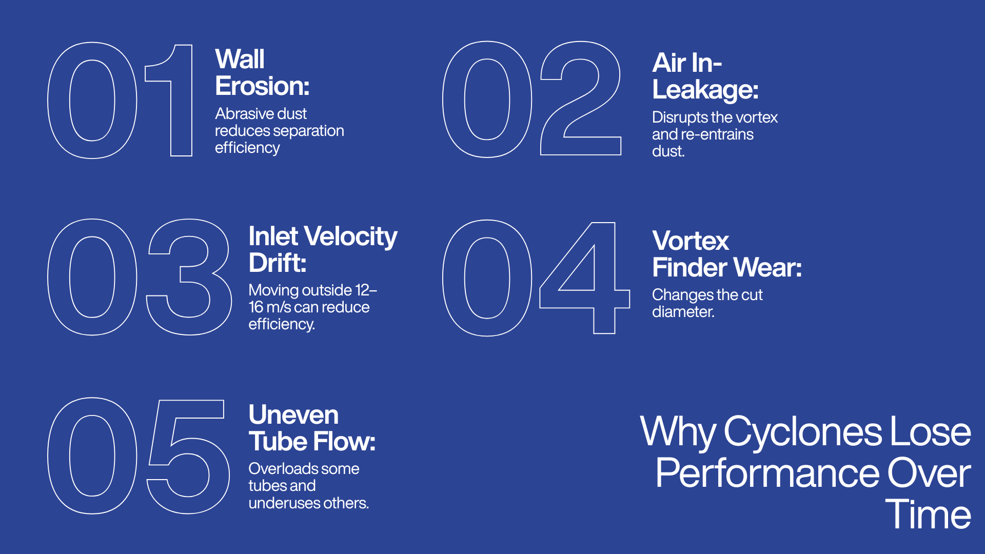
Even a well-engineered cyclone drifts from its design performance if these failure modes are left unchecked:
- Wall erosion. Abrasive dust gradually roughens the internal surface, eroding the smoothness a given d50 assumes. It accelerates sharply if inlet velocity has crept above the design target.
- Air in-leakage at the dust outlet. Even a small gap at the hopper or rotary airlock disturbs the internal vortex and re-entrains dust that had already been separated.
- Inlet velocity drift. Fan wear, ducting changes, or a downstream blockage can pull operating velocity away from the 12 to 16 m/s design band, often with no warning until efficiency has already dropped.
- Vortex finder wear or misalignment. This directly shifts the achieved cut diameter away from its design value.
- Uneven flow across multiclone tubes. Almost always traceable to plenum design, this overloads some tubes and leaves others underused.
Matching tube geometry, inlet design, and plenum sizing to a plant's actual dust and airflow, rather than shipping one universal tube across every job, is what keeps these failure modes from surfacing three or four years after commissioning. That application-specific approach is built into TECHFLOW's MultiClone range.
Selecting the Right System: The Questions That Actually Decide It
- What is the target cut diameter, specifically?
Dust predominantly above 10 μm can often run on a cyclone alone. A meaningful fraction below 5 μm means planning a cyclone as a pre-cleaner from day one, with a bag filter or ESP built into the design rather than bolted on later. - What is the airflow against available floor space?
High CFM in a tight footprint points toward a multiclone. - What is the realistic pressure drop, and what does it cost annually in fan energy?
Check it against the real fan curve and actual runtime hours, not a spec-sheet figure. - Is there a regulatory emission limit?
If a notified stack limit applies, a downstream bag filter, ESP, or scrubber belongs in the original design. - Is the dust abrasive, sticky, or combustible?
This governs tube material, wear lining, spark-trap requirements, and whether dry inertial separation is even the right technology to begin with.
The Bottom Line
Every lever in this guide traces back to the same balance between a particle's inertia and the drag of the air carrying it. A smaller diameter and a higher velocity buy a finer cut diameter, at the direct cost of higher pressure drop and, in multiclone form, more components that must stay aligned and evenly loaded. A single cyclone is the right call when the dust is coarse enough and the airflow modest enough that a standard 12 to 16 m/s design velocity already reaches the required d50. A multiclone is the right call when that cut diameter is not reachable in one body without exceeding a practical size limit or a safe velocity limit.
Neither should be asked to meet strict fine-particulate compliance on its own. That ceiling sits around 5 μm and is built into the physics, not into any manufacturer's build quality. The right response is sequencing with a bag filter or ESP downstream, not pushing inlet velocity past its erosion-safe range to chase a marginally lower d50. That is the calculation TECHFLOW runs on every project across its cyclone and MultiClone lines: tube diameter, inlet velocity, and staging matched to what a specific plant actually produces, rather than a number pulled from a generic specification sheet.
Frequently Asked Questions (FAQs)
A cyclone can run indoors as a pre-cleaning stage before ducting to a bag filter or an outdoor discharge, but it is not a standalone final-exhaust solution in an enclosed space. The sub-5 μm dust that escapes capture still needs routing to downstream filtration rather than release into the workspace.
Calculate the single-cyclone body diameter needed to reach your target cut diameter at the standard 12 to 16 m/s design velocity, then check whether that diameter can pass your total CFM without exceeding a safe velocity. If it cannot, a multi-cyclone is the answer, not a preference. TECHFLOW runs this exact calculation across its cyclone and MultiClone ranges before recommending either.
The separating force drops below what the target cut diameter requires, so particles that should be captured escape through the vortex finder. The unit runs coarser than its design rating, usually with no obvious sign that anything is wrong until dust shows at the stack.
Both. Cut diameter calculations assume a specific particle density, so lighter dust such as fine biomass ash needs a smaller diameter or a higher velocity to reach the same micron cut point as denser dust such as sand or metal fines, because the separating force scales with particle mass.
Generally no. The inlet plenum, ducting, and hopper geometry differ between the two configurations, so converting typically means a new unit rather than a retrofit. That is why getting the single-versus-multi decision right at the design stage matters.
Yes. Both gas viscosity and gas density change with temperature, and both feed into the cut-diameter relationship. Higher gas viscosity at elevated temperature tends to push the cut diameter coarser, so a cyclone handling hot boiler or kiln gas has to be sized for the actual operating temperature and gas properties, not standard ambient-air assumptions. Designing on ambient figures and then running hot is a common way to end up with a coarser real-world cut than the datasheet implies.
With no filter media or bearings on a fixed wear schedule, lifespan is governed almost entirely by the wall erosion rate, which depends on dust abrasiveness and how closely inlet velocity has been held to its design target. TECHFLOW builds application-specific tube types under its MultiClone line to account for this, rather than using one universal wall thickness across every dust type.
It can technically keep running, but performance degrades. A blocked tube forces its airflow share unevenly through the remaining tubes, pushing them above design velocity and raising both pressure drop and erosion risk on the tubes still in service.
Yes, in pneumatic conveying specifically. Here the cyclone's role shifts from waste removal to product recovery, separating conveyed material from the transport air stream at the end of a line so the material can be collected rather than treated as dust to discard.
Because separation happens through inertia and geometry, not filtration through a fabric medium, there is no filter surface to load with dust and no bags to periodically clean or replace. A bag filter, by contrast, traps dust on a fabric surface that must be pulse-cleaned and eventually renewed.
Usually not. A standalone cyclone leaves outlet loading well above most notified limits. On a regulated stack, the cyclone or multiclone acts as the primary separator, with a bag filter or electrostatic precipitator downstream sized to bring the outlet down to the compliance limit set by the Central Pollution Control Board and enforced by the State Pollution Control Board.


